PROGRAMMING GUIDE
SINUS PENTA
395/486
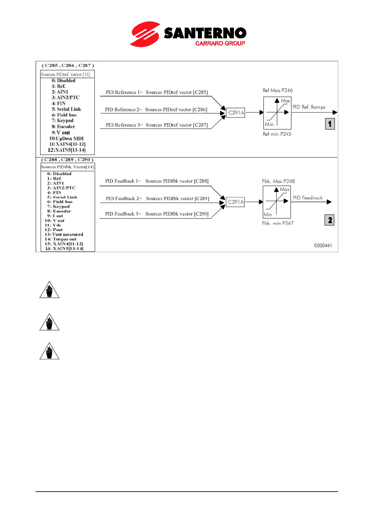
Figure 70: Reference source and feedback source selection
NOTE
The signals selected in the Sources Vector are to be considered as percentage values;
therefore, analog signals are expressed as a percentage of the preset maximum values
and minimum values. For example, when selecting a reference source, if P052 Ref. max.
= 8V and P051 Ref. min. = –3V, 100% will be considered when Ref. = 8V and –100% will
be considered when Ref. = –3V.
NOTE
Among the allowable variables for the PID feedback, electrical variables Iout (output
current), Vout (output voltage), Vdc (DC bus voltage), Pout (output power) and Torque
out (output torque – only with VTC and FOC control).
Their percentage values relate to rated current values and rated voltage values of the
selected motor and to 1500VDC respectively.
NOTE
In Local mode, the PID regulator is disabled if set as C294 = Add Reference or Add
Voltage.
Block 3: PID Control Mode
This block allows applying different processing types to the feedback signals and allows enabling/disabling the PID2
integrated into the system (see C291a).
Block 4: Ramp over PID Reference
A ramp may be applied to the PID references sent from block 3. The same ramp is applicable for both blocks: the
processed references are the ones actually used in the PID regulator. The parameters of the PID reference ramp are
illustrated in the figure below. The initial rounding-off is applied to the reference whenever a new
acceleration/deceleration ramp is started, while the end reference is applied at the end of each ramp.