PROGRAMMING GUIDE
SINUS PENTA
435/486
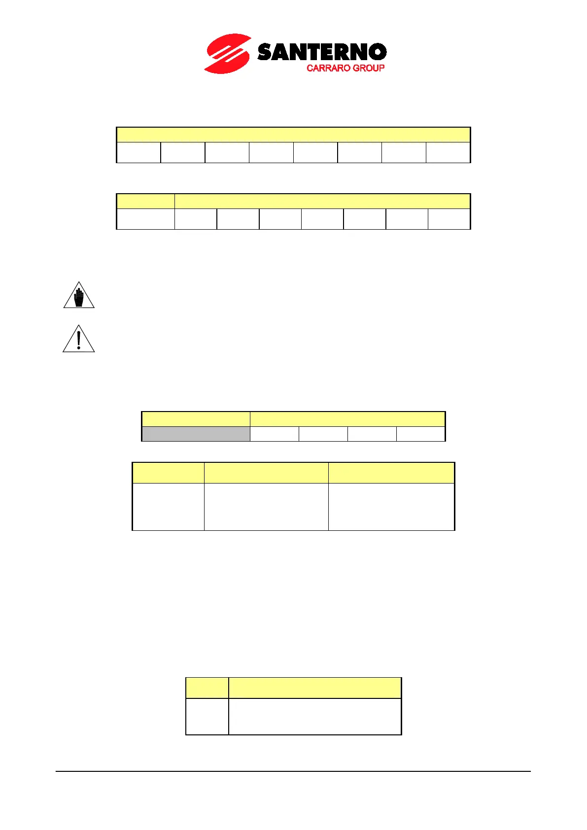
Word 5: Digital Inputs from FIELDBUS
The virtual digital inputs via the Fieldbus are the low byte of the word:
bit [7..0]
MDI8 MDI7 MDI6 MDI5 MDI4
MDI2 MDI1
The virtual auxiliary digital inputs from Fieldbus are given in the high byte of the word:
bit 15 bit [14..8]
XMDI7 XMDI6 XMDI5 XMDI4 XMDI3 XMDI2 XMDI1
The logic status of these bits is included in the overall status of the drive digital inputs (measure M031) along with the
other command sources if at least one of the parameters C140 ÷ C142 is set as 6:FieldBus.
NOTE
Auxiliary digital input XMDI8, allocated to bit 15 of Word 5, may be controlled only
if:
R016 = 0 (inactive watchdog), or
R016 > 0 (active watchdog) and R018b = 2.
CAUTION
If R016 > 0 (active watchdog), bit 15 is controlled via parameter R018b:
• R018b = 0/1: see the description of the parameter
• R018b = 2: the bit controls input XMDI8 and is independent of the watchdog
Word 6: Command for Digital Outputs from FIELDBUS
Digital commands from FIELDBUS are the 4 lower bytes of the word:
bit [15...4] bit [3..0]
CMD 4 CMD 3 CMD 2 CMD 1
Byte format:
Bit Command
Position in the selection
vector
Columns 2 and 3 state the name and position of the commands sent via fieldbus.
Example: to control digital output 1 via fieldbus through command 4, set the parameters below in the DIGITAL
OUTPUTS MENU:
P270 = 1: Digital Digital Output Mode
P271 = D37: Fbus CMD4 Variable A Selection
P278 = 1: True Output Logic Level
Words 7, 8, 9: Analog Outputs controlled by FIELDBUS
Parameter R017 needs to be properly set up to distinguish which Analog Outputs are to be controlled by the Fieldbus.
Byte format:
Bit Analog Output controlled by the fieldbus
Example: R017 = 011
2
= 3
10
→ analog outputs AO1 and AO2 are controlled directly by the fieldbus, independently of
their configuration in the ANALOG AND FREQUENCY OUTPUTS MENU.