RM0033 Rev 9 229/1381
RM0033 Analog-to-digital converter (ADC)
255
Dual ADC mode
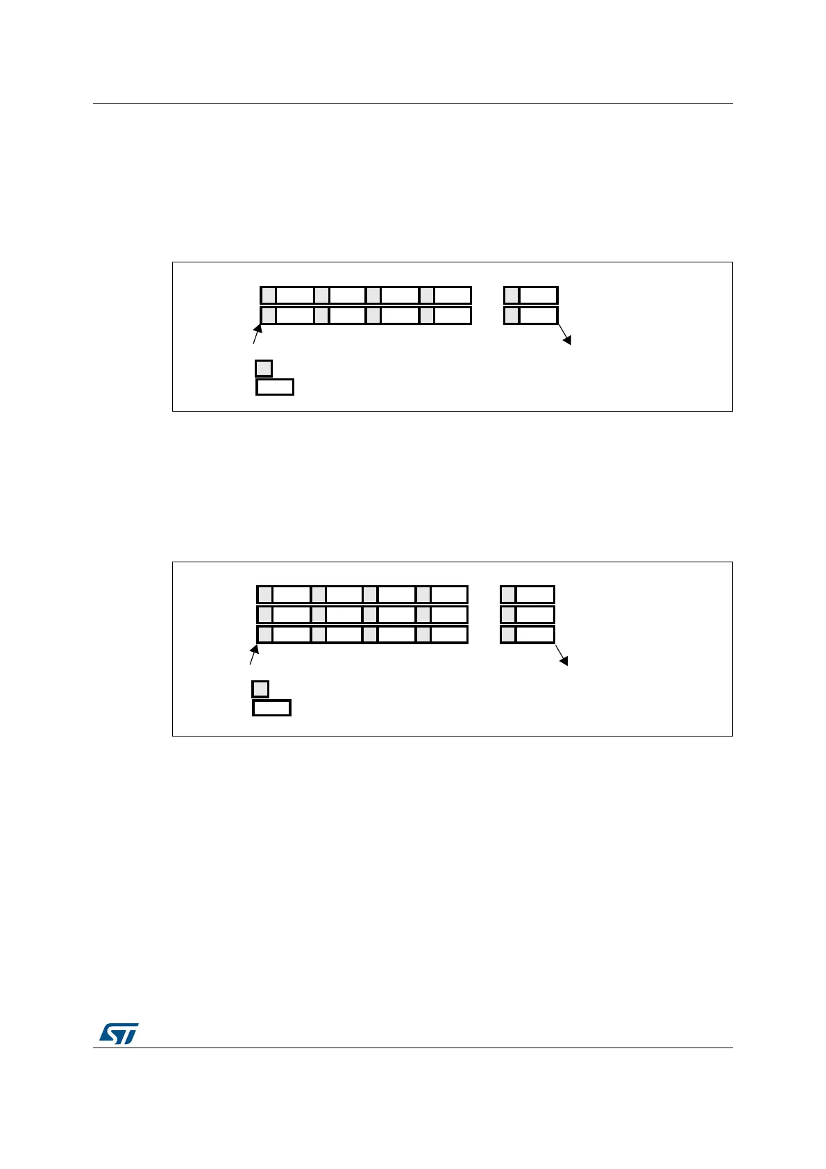
At the end of conversion event on ADC1 or ADC2:
• The converted data are stored into the ADC_JDRx registers of each ADC interface.
• A JEOC interrupt is generated (if enabled on one of the two ADC interfaces) when the
ADC1/ADC2’s injected channels have all been converted.
Figure 36. Injected simultaneous mode on 4 channels: dual ADC mode
Triple ADC mode
At the end of conversion event on ADC1, ADC2 or ADC3:
• The converted data are stored into the ADC_JDRx registers of each ADC interface.
• A JEOC interrupt is generated (if enabled on one of the three ADC interfaces) when the
ADC1/ADC2/ADC3’s injected channels have all been converted.
Figure 37. Injected simultaneous mode on 4 channels: triple ADC mode
10.9.2 Regular simultaneous mode
This mode is performed on a regular group of channels. The external trigger source comes
from the regular group multiplexer of ADC1 (selected by the EXTSEL[3:0] bits in the
ADC1_CR2 register). A simultaneous trigger is provided to ADC2 and ADC3.
Note: Do not convert the same channel on the two/three ADCs (no overlapping sampling times for
the two/three ADCs when converting the same channel).
In regular simultaneous mode, one must convert sequences with the same length or ensure
that the interval between triggers is longer than the long conversion time of the 2 sequences
(Dual ADC mode) /3 sequences (Triple ADC mode). Otherwise, the ADC with the shortest
sequence may restart while the ADC with the longest sequence is completing the previous
conversions.
Injected conversions must be disabled.
CH0 CH1 CH2 CH3
CH15 CH14 CH13 CH12
ADC1
ADC2
Trigger
End of conversion on ADC1 and ADC2
Conversion
Sampling
CH15
CH0
...
...
ai16054
CH0 CH1 CH2 CH3
CH15 CH14 CH13 CH12
ADC1
ADC2
Trigger
End of conversion on ADC1, ADC2 and ADC3
Conversion
Sampling
CH15
CH0
...
...
ai16055
CH10 CH12 CH8 CH5
ADC3
CH2
...
 Loading...


