RM0033 Rev 9 75/1381
RM0033 Power control (PWR)
83
Exiting Stop mode
The Stop mode is exited according to Section : Exiting low-power mode.
Refer to Table 10 for more details on how to exit Stop mode.
When exiting Stop mode by issuing an interrupt or a wakeup event, the HSI RC oscillator is
selected as system clock.
When the voltage regulator operates in low-power mode, an additional startup delay is
incurred when waking up from Stop mode. By keeping the internal regulator ON during Stop
mode, the consumption is higher although the startup time is reduced.
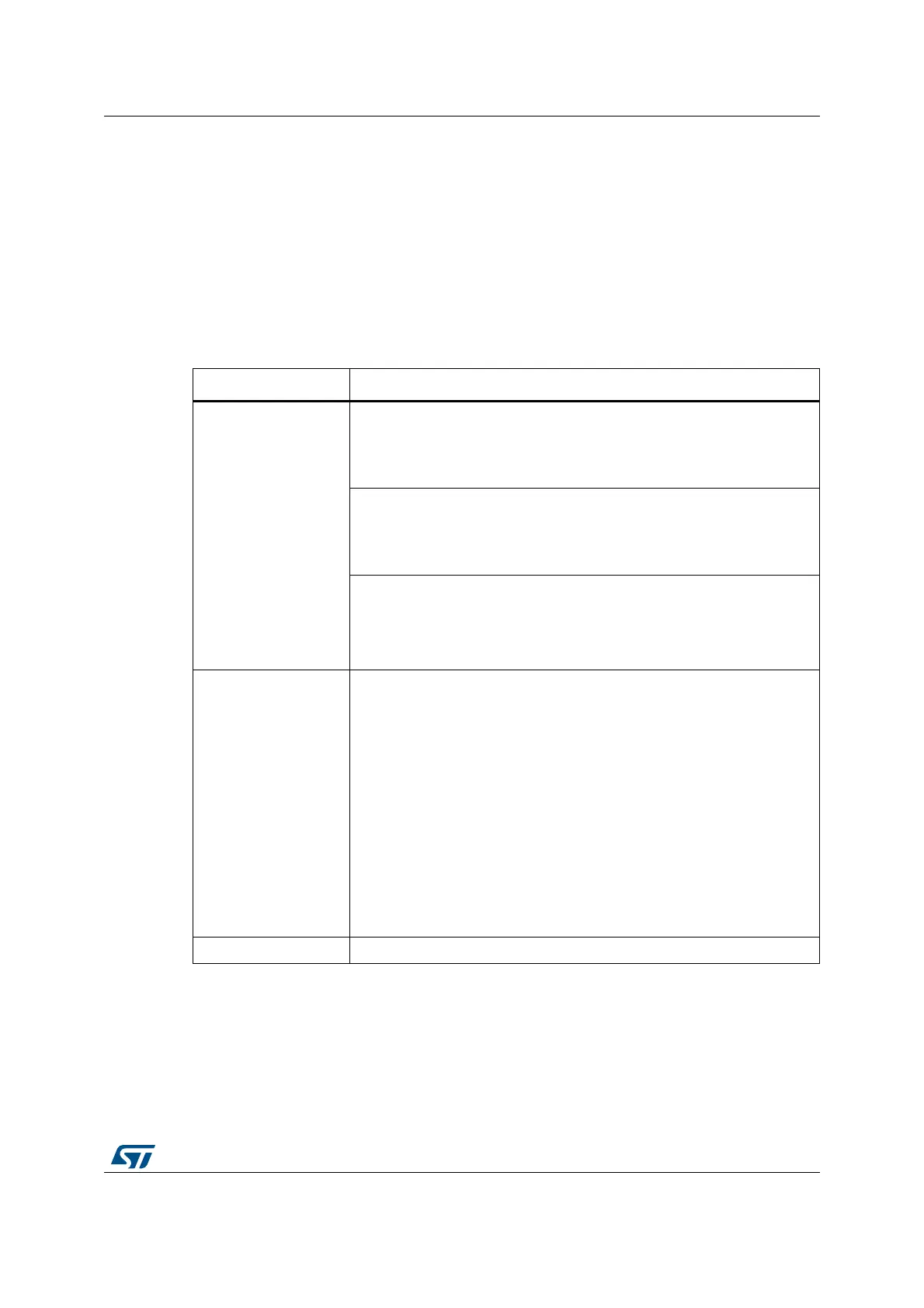
Table 10. Stop mode
Stop mode Description
Mode entry
WFI (Wait for Interrupt) or WFE (Wait for Event) while:
– SLEEPDEEP bit is set in Cortex
®
-M3 System Control register
– PDDS bit is cleared in Power Control register (PWR_CR)
– Select the voltage regulator mode by configuring LPDS bit in PWR_CR.
On Return from ISR:
– SLEEPDEEP bit is set in Cortex
®
-M3 System Control register
– SLEEPONEXIT = 1
– PDDS bit is cleared in Power Control register (PWR_CR)
Note: To enter Stop mode, all EXTI Line pending bits (in Section 8.3.6:
Pending register (EXTI_PR)), all peripheral interrupts pending bits,
the RTC Alarm (Alarm A and Alarm B), RTC wakeup, RTC tamper,
and RTC time stamp flags, must be reset. Otherwise, the Stop
mode entry procedure is ignored and program execution continues.
Mode exit
If WFI or return from ISR was used for entry:
Any EXTI lines configured in Interrupt mode (the corresponding EXTI
Interrupt vector must be enabled in the NVIC). The interrupt source can
be external interrupts or peripherals with wakeup capability. Refer to
Table 20: Vector table on page 164.
If WFE was used for entry and SEVONPEND = 0
Any EXTI lines configured in event mode. Refer to Section 8.3.6:
Pending register (EXTI_PR).
If WFE was used for entry and SEVONPEND = 1:
– Any EXTI lines configured in Interrupt mode (even if the corresponding
EXTI Interrupt vector is disabled in the NVIC). The interrupt source can
be an external interrupt or a peripheral with wakeup capability. Refer to
Table 20: Vector table on page 164
Wakeup event: refer to Section 8.2.3: Wakeup event management
Wakeup latency HSI RC wakeup time + regulator wakeup time from Low-power mode
 Loading...


