USB on-the-go full-speed (OTG_FS) RM0033
962/1381 RM0033 Rev 9
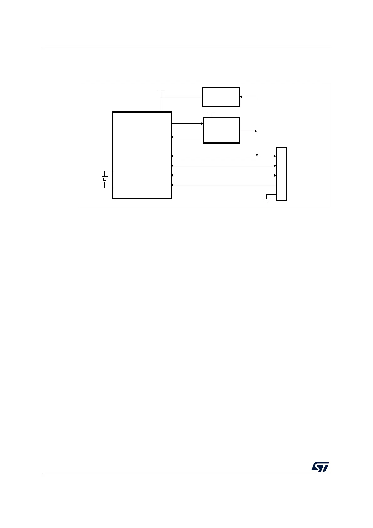
29.4 OTG dual role device (DRD)
Figure 350. OTG A-B device connection
1. External voltage regulator only needed when building a V
BUS
powered device
2. STMPS2141STR needed only if the application has to support a V
BUS
powered device. A basic power
switch can be used if 5 V are available on the application board.
29.4.1 ID line detection
The host or peripheral (the default) role is assumed depending on the ID input pin
(OTG_FS_ID). The ID line status is determined on plugging in the USB, depending on which
side of the USB cable is connected to the micro-AB receptacle.
• If the B-side of the USB cable is connected with a floating ID wire, the integrated pull-
up resistor detects a high ID level and the default Peripheral role is confirmed. In this
configuration the OTG_FS complies with the standard FSM described by section 6.8.2:
On-The-Go B-device of the On-The-Go Specification Rev1.3 supplement to the
USB2.0.
• If the A-side of the USB cable is connected with a grounded ID, the OTG_FS issues an
ID line status change interrupt (CIDSCHG bit in OTG_FS_GINTSTS) for host software
initialization, and automatically switches to the host role. In this configuration the
OTG_FS complies with the standard FSM described by section 6.8.1: On-The-Go A-
device of the On-The-Go Specification Rev1.3 supplement to the USB2.0.
29.4.2 HNP dual role device
The HNP capable bit in the Global USB configuration register (HNPCAP bit in OTG_FS_
GUSBCFG) enables the OTG_FS core to dynamically change its role from A-host to A-
peripheral and vice-versa, or from B-Peripheral to B-host and vice-versa according to the
host negotiation protocol (HNP). The current device status can be read by the combined
values of the Connector ID Status bit in the Global OTG control and status register (CIDSTS
bit in OTG_FS_GOTGCTL) and the current mode of operation bit in the global interrupt and
status register (CMOD bit in OTG_FS_GINTSTS).
The HNP program model is described in detail in Section 29.17: OTG_FS programming
model.
STM32 MCU
STMPS2141STR
Current-limited
power distribution
switch
(2)
V
DD
VBUS
DP
V
SS
PA9
PA1 2
PA1 1
USB micro-AB
connector
DM
GPIO+IRQ
GPIO
EN
Overcurrent
5 V Pwr
5 V to V
DD
voltage regulator
V
DD
ID
PA1 0
OSC_IN
OSC_OUT
MS19904V4