Serial peripheral interface (SPI) RM0033
712/1381 RM0033 Rev 9
For transmission, each time an MSB is written to SPI_DR, the TXE flag is set and its
interrupt, if allowed, is generated to load SPI_DR with the new value to send. This takes
place even if 0x0000 have not yet been sent because it is done by hardware.
For reception, the RXNE flag is set and its interrupt, if allowed, is generated when the first
16 MSB half-word is received.
In this way, more time is provided between two write or read operations, which prevents
underrun or overrun conditions (depending on the direction of the data transfer).
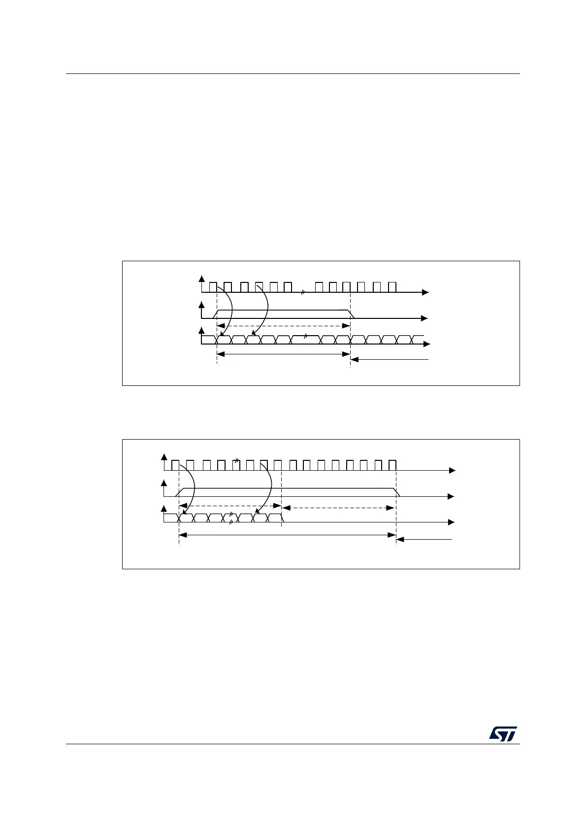
MSB justified standard
For this standard, the WS signal is generated at the same time as the first data bit, which is
the MSBit.
Figure 271. MSB justified 16-bit or 32-bit full-accuracy length with CPOL = 0
Data are latched on the falling edge of CK (for transmitter) and are read on the rising edge
(for the receiver).
Figure 272. MSB justified 24-bit frame length with CPOL = 0
MS30100 V1
CK
WS
SD
Transmission
Reception
16- or 32 bit data
MSB
LSB
Channel left
Channel right
MSB
MS30101V1
CK
WS
SD
Transmission
Reception
24 bit data
MSB
LSB
Channel left 32-bit
Channel right
8-bit remaining
0 forced
 Loading...


