Memory and bus architecture RM0033
58/1381 RM0033 Rev 9
2.3.5 Adaptive real-time memory accelerator (ART Accelerator™)
The ART Accelerator™ is a memory accelerator which is optimized for STM32 industry-
standard Arm
®
Cortex
®
-M3 processors. It balances the inherent performance advantage of
the Arm
®
Cortex
®
-M3 over Flash memory technologies, which normally requires the
processor to wait for the Flash memory at higher operating frequencies. Thanks to the ART
Accelerator™, the CPU can operate up to 120 MHz without wait states, thereby increasing
the overall system speed and efficiency.
To release the processor full 150 DMIPS performance at this frequency the accelerator
implements an instruction prefetch queue and branch cache, which enables program
execution from Flash memory at up to 120 MHz without wait states.
2.4 Boot configuration
Due to its fixed memory map, the code area starts from address 0x0000 0000 (accessed
through the ICode/DCode buses) while the data area (SRAM) starts from address
0x2000 0000 (accessed through the system bus). The Cortex
®
-M3 CPU always fetches the
reset vector on the ICode bus, which implies to have the boot space available only in the
code area (typically, Flash memory). STM32F20x and STM32F21x microcontrollers
implement a special mechanism to be able to boot from other memories (like the internal
SRAM).
In the STM32F20x and STM32F21x, three different boot modes can be selected through the
BOOT[1:0] pins as shown in Table 4.
Bit 8 PRFTEN: Prefetch enable
0: Prefetch is disabled
1: Prefetch is enabled
Bits 7:3 Reserved, must be kept cleared.
Bits 2:0 LATENCY: Latency
These bits represent the ratio of the CPU clock period to the Flash memory access time.
000: Zero wait state
001: One wait state
010: Two wait states
011: Three wait states
100: Four wait states
101: Five wait states
110: Six wait states
111: Seven wait states
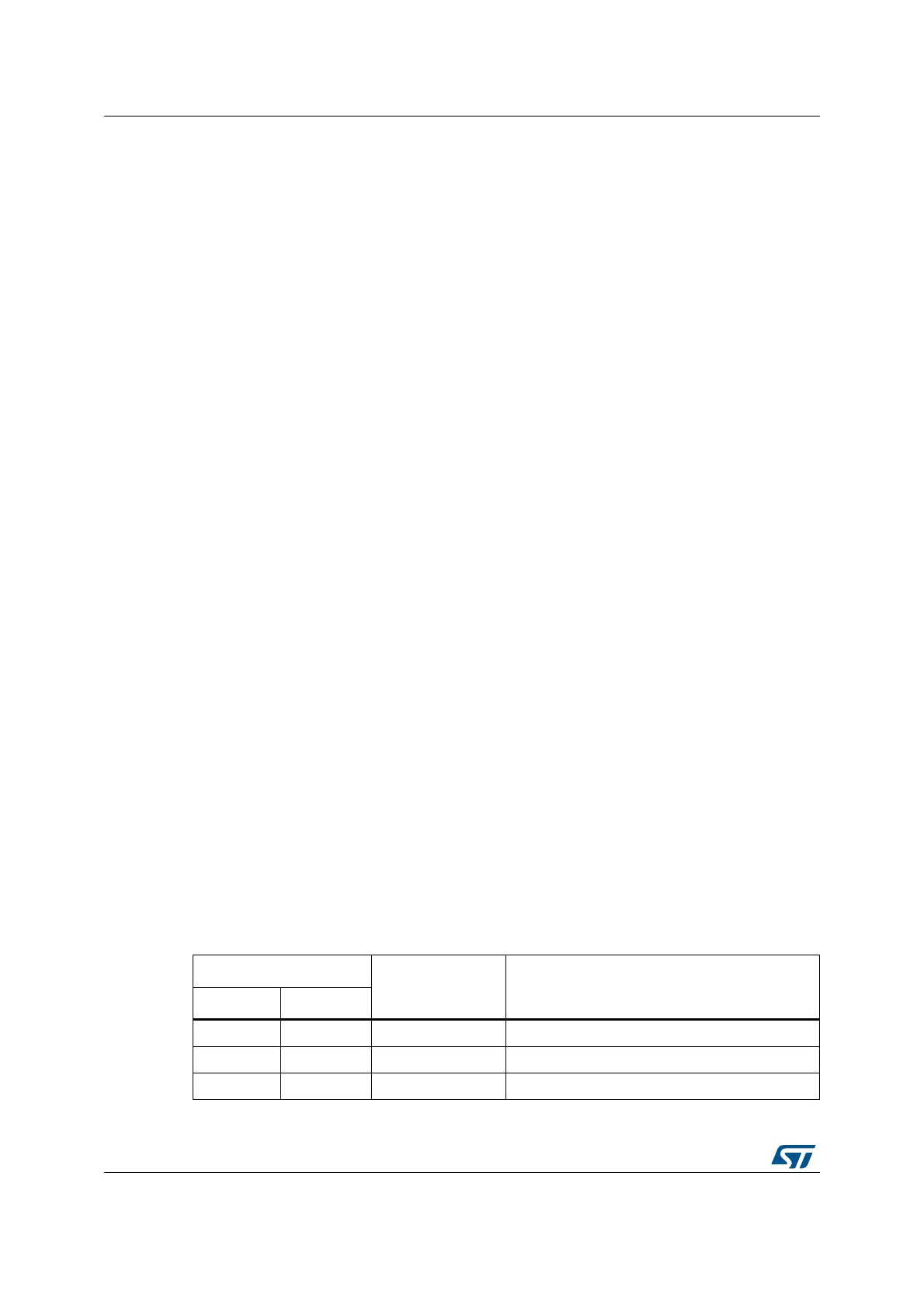
Table 4. Boot modes
Boot mode selection pins
Boot mode Aliasing
BOOT1 BOOT0
x 0 Main Flash memory Main Flash memory is selected as the boot space
0 1 System memory System memory is selected as the boot space
1 1 Embedded SRAM Embedded SRAM is selected as the boot space
 Loading...


