RM0033 Rev 9 379/1381
RM0033 General-purpose timers (TIM2 to TIM5)
436
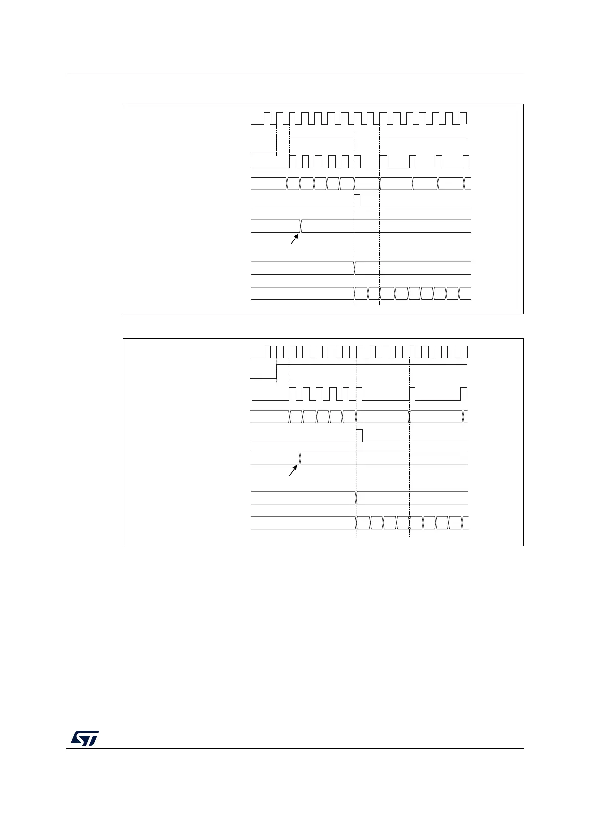
Figure 114. Counter timing diagram with prescaler division change from 1 to 2
Figure 115. Counter timing diagram with prescaler division change from 1 to 4
14.3.2 Counter modes
Upcounting mode
In upcounting mode, the counter counts from 0 to the auto-reload value (content of the
TIMx_ARR register), then restarts from 0 and generates a counter overflow event.
An Update event can be generated at each counter overflow or by setting the UG bit in the
TIMx_EGR register (by software or by using the slave mode controller).
The UEV event can be disabled by software by setting the UDIS bit in TIMx_CR1 register.
This is to avoid updating the shadow registers while writing new values in the preload
registers. Then no update event occurs until the UDIS bit has been written to 0. However,
the counter restarts from 0, as well as the counter of the prescaler (but the prescale rate
MS35833V1
CK_PSC
00
CNT_EN
Timerclock = CK_CNT
Counter register
Update event (UEV)
0
Prescaler control register
1
0
Write a new value in TIMx_PSC
Prescaler buffer
1
0
Prescaler counter
01010101
01 02 03FA FBF7 F8 F9 FC
MS35834V1
0
30
01230123
CK_PSC
CNT_EN
Timerclock = CK_CNT
Counter register
Update event (UEV)
Prescaler control register
Write a new value in TIMx_PSC
Prescaler buffer
Prescaler counter
00 01FA FBF7 F8 F9 FC
30
 Loading...


