RM0033 Rev 9 237/1381
RM0033 Analog-to-digital converter (ADC)
255
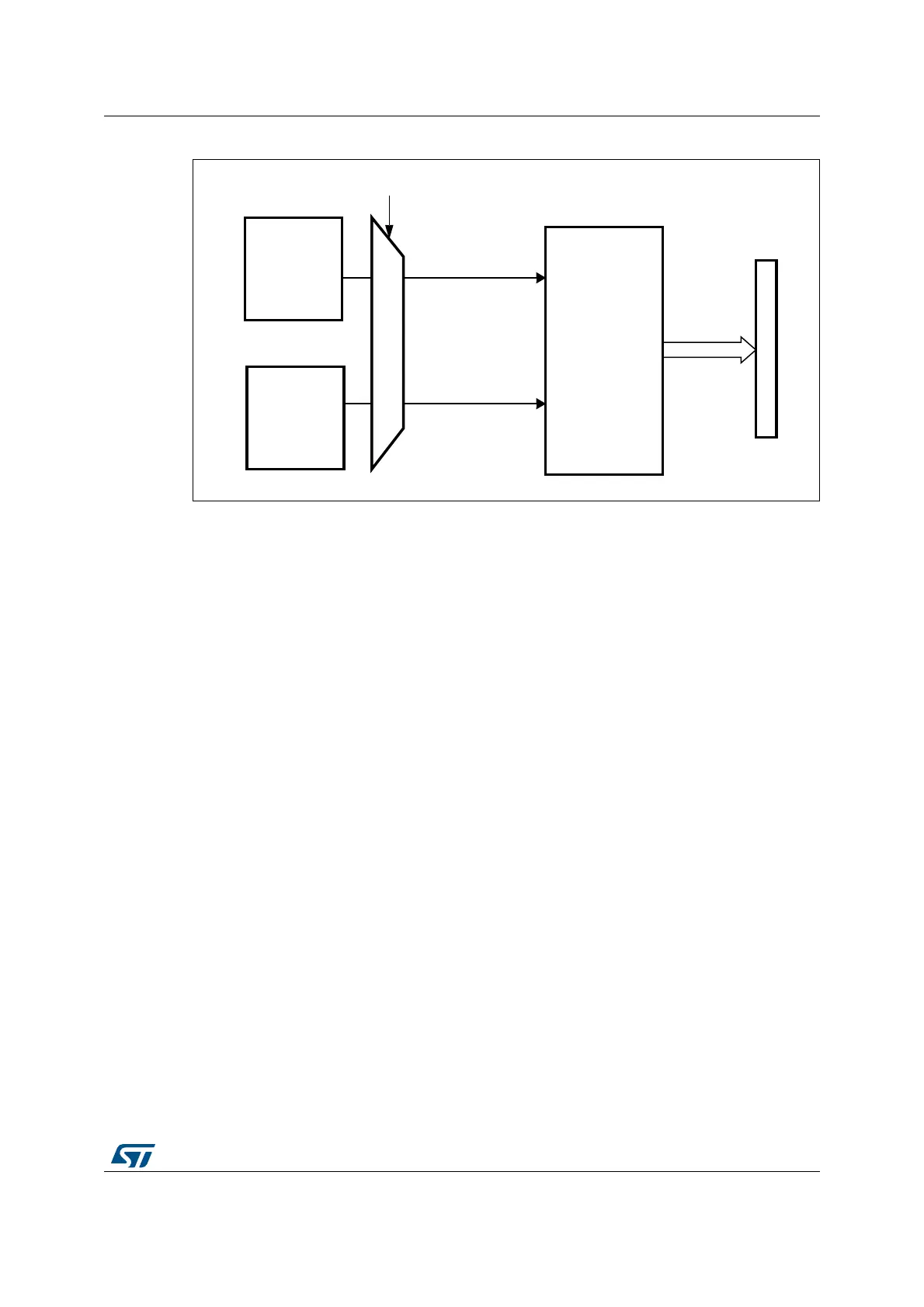
Figure 47. Temperature sensor and V
REFINT
channel block diagram
Reading the temperature
To use the sensor:
1. Select ADC1_IN16 input channel.
2. Select a sampling time greater than the minimum sampling time specified in the
datasheet.
3. Set the TSVREFE bit in the ADC_CCR register to wake up the temperature sensor
from power down mode
4. Start the ADC conversion by setting the SWSTART bit (or by external trigger)
5. Read the resulting V
SENSE
data in the ADC data register
6. Calculate the temperature using the following formula:
Temperature (in °C) = {(V
SENSE
– V
25
) / Avg_Slope} + 25
Where:
–V
25
= V
SENSE
value for 25° C
– Avg_Slope = average slope of the temperature vs. V
SENSE
curve (given in mV/°C
or µV/°C)
Refer to the datasheet’s electrical characteristics section for the actual values of V
25
and Avg_Slope.
Note: The sensor has a startup time after waking from power down mode before it can output
V
SENSE
at the correct level. The ADC also has a startup time after power-on, so to minimize
the delay, the ADON and TSVREFE bits should be set at the same time.
The temperature sensor output voltage changes linearly with temperature. The offset of this
linear function depends on each chip due to process variation (up to 45 °C from one chip to
another).
The internal temperature sensor is more suited for applications that detect temperature
variations instead of absolute temperatures. If accurate temperature reading is required, an
external temperature sensor should be used.
sensor
Temper ature
V
SENSE
TSVREFE control bit
ADC1
Address/data bus
converted data
V
REFINT
ADC1_IN16
ADC1_IN17
power
block
Internal
ai16065
 Loading...


