Serial peripheral interface (SPI) RM0033
716/1381 RM0033 Rev 9
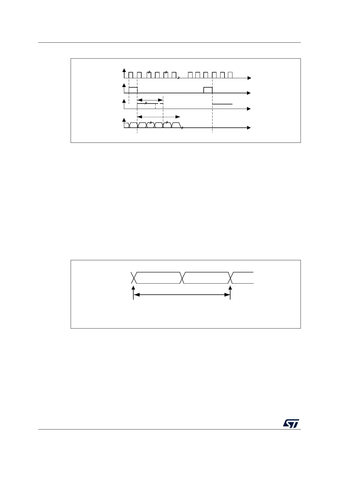
Figure 281. PCM standard waveforms (16-bit extended to 32-bit packet frame)
Note: For both modes (master and slave) and for both synchronizations (short and long), the
number of bits between two consecutive pieces of data (and so two synchronization signals)
needs to be specified (DATLEN and CHLEN bits in the SPI_I2SCFGR register) even in
slave mode.
25.4.3 Clock generator
The I
2
S bitrate determines the dataflow on the I
2
S data line and the I
2
S clock signal
frequency.
I
2
S bitrate = number of bits per channel × number of channels × sampling audio frequency
For a 16-bit audio, left and right channel, the I
2
S bitrate is calculated as follows:
I
2
S bitrate = 16 × 2 × F
S
It will be: I
2
S bitrate = 32 x 2 x F
S
if the packet length is 32-bit wide.
Figure 282. Audio sampling frequency definition
When the master mode is configured, a specific action needs to be taken to properly
program the linear divider in order to communicate with the desired audio frequency.
MS30107V1
CK
WS
short frame
SD
WS
long frame
Up to 13-bits
MSB
LSB
16 bits
MS30108V1
16-or 32-bit left
channel
16-or 32-bit
right channel
32- or 64-bits
sampling point
sampling point
F
S
F
S
: audio sampling frequency
 Loading...


