RM0033 Rev 9 67/1381
RM0033 Power control (PWR)
83
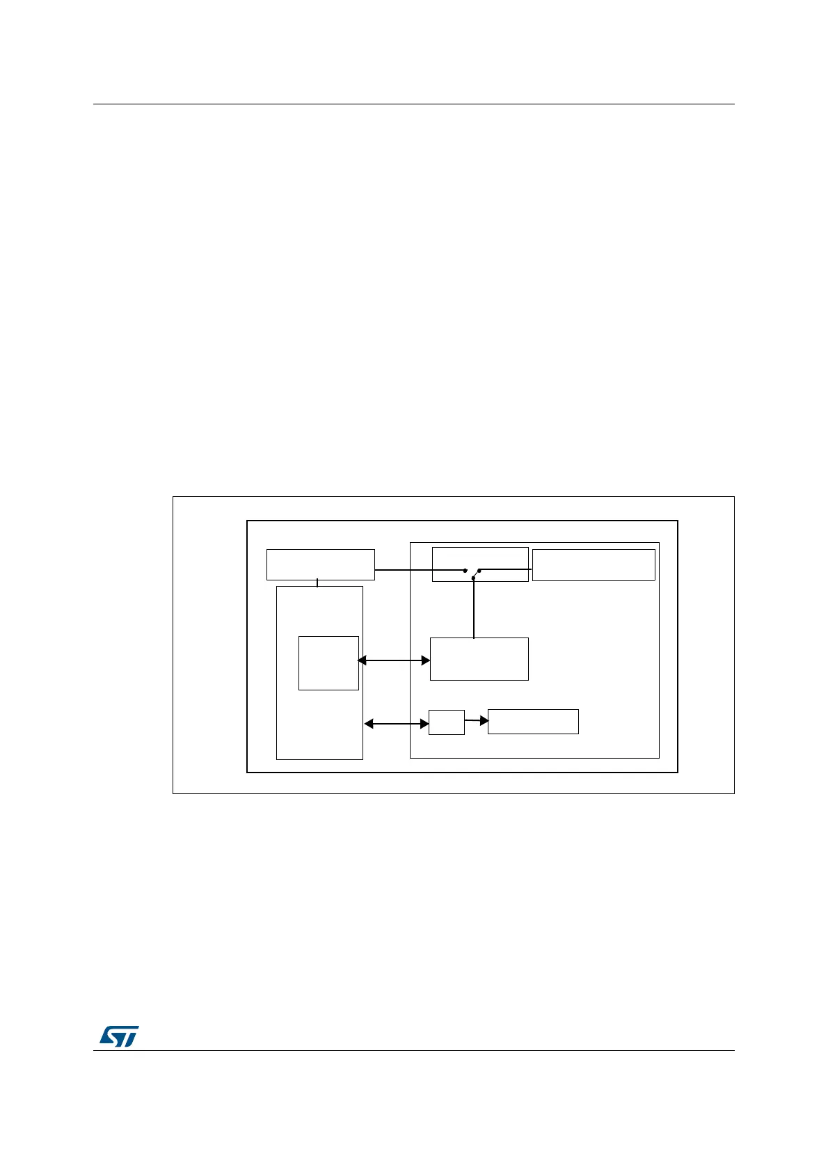
Backup SRAM
The backup domain includes 4 Kbytes of backup SRAM addressed in 32-bit, 16-bit or 8-bit
mode. Its content is retained even in Standby or V
BAT
mode when the low-power backup
regulator is enabled. It can be considered as an internal EEPROM when V
BAT
is always
present.
When the backup domain is supplied by V
DD
(analog switch connected to V
DD
), the backup
SRAM is powered from V
DD
which replaces the V
BAT
power supply to save battery life.
When the backup domain is supplied by V
BAT
(analog switch connected to V
BAT
because
V
DD
is not present), the backup SRAM is powered by a dedicated low-power regulator. This
regulator can be ON or OFF depending whether the application needs the backup SRAM
function in Standby and V
BAT
modes or not. The power down of this regulator is controlled
by a dedicated bit, the BRE control bit of the PWR_CSR register (see Section 4.4.2: PWR
power control/status register (PWR_CSR)).
The backup SRAM is not mass erased by an tamper event. It is read protected to prevent
confidential data, such as cryptographic private key, from being accessed. The backup
SRAM can be erased only through the Flash interface when a protection level change from
level 1 to level 0 is requested. Refer to the description of Read protection (RDP) in the Flash
programming manual.
Figure 4. Backup SRAM
4.1.3 Voltage regulator
An embedded linear voltage regulator supplies all the digital circuitries except for the backup
domain and the Standby circuitry. The regulator output voltage is 1.2 V.
This voltage regulator requires two external capacitors to be connected to two dedicated
pins, V
CAP_1
and V
CAP_2
available in all packages.
Voltage Regulator
Backup domain
1.2 V domain
BACKUP SRAM
1.2 V
BACKUP
SRAM
Interface
3.3->1.2
LP Voltage Regulator
3.3->1.2
RTC
LSE 32.768 Hz
Power Switch
 Loading...


