Analog-to-digital converter (ADC) RM0033
230/1381 RM0033 Rev 9
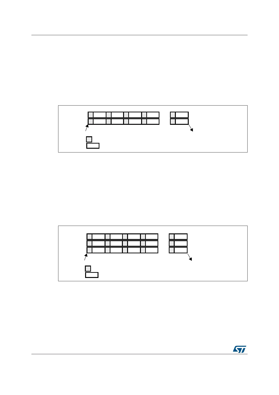
Dual ADC mode
At the end of conversion event on ADC1 or ADC2:
• A 32-bit DMA transfer request is generated (if DMA[1:0] bits in the ADC_CCR register
are equal to 0b10). This request transfers the ADC2 converted data stored in the upper
half-word of the ADC_CDR 32-bit register to the SRAM and then the ADC1 converted
data stored in the lower half-word of ADC_CDR to the SRAM.
• An EOC interrupt is generated (if enabled on one of the two ADC interfaces) when the
ADC1/ADC2’s regular channels have all been converted.
Figure 38. Regular simultaneous mode on 16 channels: dual ADC mode
Triple ADC mode
At the end of conversion event on ADC1, ADC2 or ADC3:
• Three 32-bit DMA transfer requests are generated (if DMA[1:0] bits in the ADC_CCR
register are equal to 0b01). Three transfers then take place from the ADC_CDR 32-bit
register to SRAM: first the ADC1 converted data, then the ADC2 converted data and
finally the ADC3 converted data. The process is repeated for each new three
conversions.
• An EOC interrupt is generated (if enabled on one of the three ADC interfaces) when the
ADC1/ADC2/ADC3’s regular channels are have all been converted.
Figure 39. Regular simultaneous mode on 16 channels: triple ADC mode
CH0 CH1 CH2 CH3
CH15 CH14 CH13 CH12
ADC1
ADC2
Trigger
End of conversion on ADC1 and ADC2
Conversion
Sampling
CH15
CH0
...
...
ai16054
CH0 CH1 CH2 CH3
CH15 CH14 CH13 CH12
ADC1
ADC2
Trigger
End of conversion on ADC1, ADC2 and ADC3
Conversion
Sampling
CH15
CH0
...
...
ai16055
CH10 CH12 CH8 CH5
ADC3
CH2
...
 Loading...


