Serial peripheral interface (SPI) RM0033
692/1381 RM0033 Rev 9
Receive sequence
For the receiver, when data transfer is complete:
• The data in the shift register is transferred to the RX Buffer and the RXNE flag is set
• An interrupt is generated if the RXNEIE bit is set in the SPI_CR2 register
At the last sampling clock edge the RXNE bit is set, a copy of the data byte received in the
shift register is moved to the Rx buffer. When the SPI_DR register is read, the SPI
peripheral returns this buffered value.
Clearing the RXNE bit is performed by reading the SPI_DR register.
A continuous transmit stream can be maintained if the next data to be transmitted is put in
the Tx buffer once the transmission is started. Note that TXE flag should be ‘1 before any
attempt to write the Tx buffer is made.
Note: When a master is communicating with SPI slaves which need to be de-selected between
transmissions, the NSS pin must be configured as GPIO or another GPIO must be used and
toggled by software.
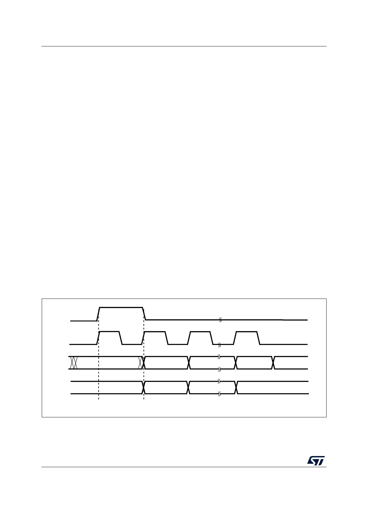
SPI TI protocol in master mode
In master mode, the SPI interface is compatible with the TI protocol. The FRF bit of the
SPI_CR2 register can be used to configure the master SPI serial communications to be
compliant with this protocol.
The clock polarity and phase are forced to conform to the TI protocol requirements whatever
the values set in the SPI_CR1 register. NSS management is also specific to the TI protocol
which makes the configuration of NSS management through the SPI_CR1 and SPI_CR2
registers (SSM, SSI, SSOE) transparent for the user.
Figure 253: TI mode - master mode, single transfer and Figure 254: TI mode - master mode,
continuous transfer) show the SPI master communication waveforms when the TI mode is
selected in master mode.
Figure 253. TI mode - master mode, single transfer
ai18436
MSBIN
MOSI
input
NSS
output
SCK
output
trigger
edge
sampling
edge
trigger
edge
sampling
edge
trigger
edge
sampling
edge
DONTCARE LSBIN DONTCARE
MISO
output
1 or 0 MSBOUT
LSBOUT
 Loading...


