RM0033 Rev 9 321/1381
RM0033 Advanced-control timers (TIM1 and TIM8)
375
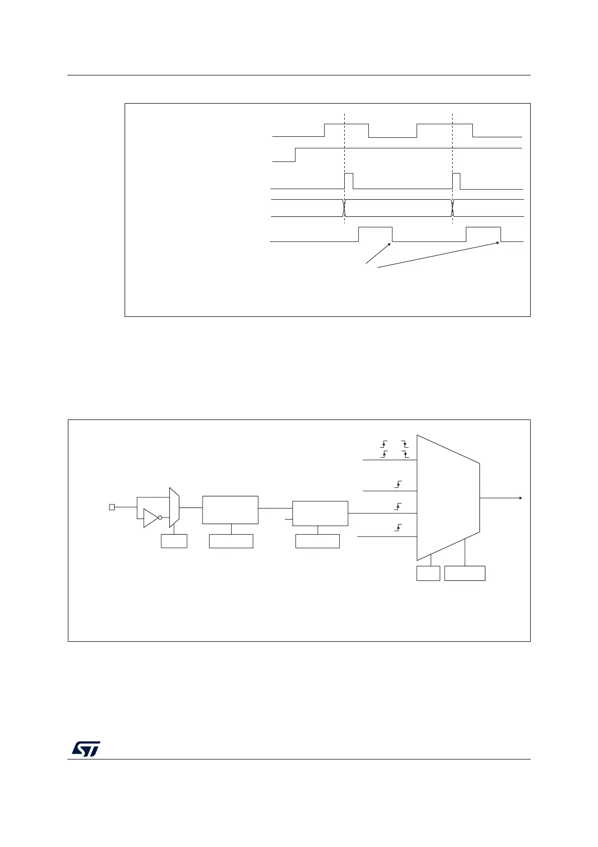
Figure 88. Control circuit in external clock mode 1
External clock source mode 2
This mode is selected by writing ECE=1 in the TIMx_SMCR register.
The counter can count at each rising or falling edge on the external trigger input ETR.
Figure 89 gives an overview of the external trigger input block.
Figure 89. External trigger input block
Counter clock = CK_CNT = CK_PSC
Counter register
35 3634
TI2
CNT_EN
TIF
Write TIF=0
MS31087V2
External clock
mode 1
Internal clock
mode
TRGI
CK_INT
CK_PSC
TIMx_SMCR
SMS[2:0]
MS33116V1
(internal clock)
TI1F or
TI2F or
or
Encoder
mode
External clock
mode 2
ETRF
ECE
0
1
TIMx_SMCR
ETP
ETR pin
ETR
Divider
/1, /2, /4, /8
Filter
downcounter
f
ETRP
TIMx_SMCR
ETPS[1:0]
TIMx_SMCR
ETF[3:0]
DTS
 Loading...


