RM0033 Rev 9 699/1381
RM0033 Serial peripheral interface (SPI)
734
1. Set the RXONLY bit in the SPI_CR1 register.
2. Enable the SPI by setting the SPE bit to 1:
a) In master mode, this immediately activates the generation of the SCK clock, and
data are serially received until the SPI is disabled (SPE=0).
b) In slave mode, data are received when the SPI master device drives NSS low and
generates the SCK clock.
3. Wait until RXNE=1 and read the SPI_DR register to get the received data (this clears
the RXNE bit). Repeat this operation for each data item to be received.
This procedure can also be implemented using dedicated interrupt subroutines launched at
each rising edge of the RXNE flag.
Note: If it is required to disable the SPI after the last transfer, follow the recommendation
described in Section 25.3.8.
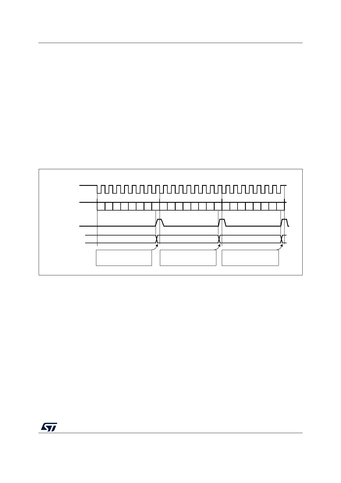
Figure 259. RXNE behavior in receive-only mode (BIDIRMODE=0 and RXONLY=1)
in case of continuous transfers
Bidirectional receive procedure (BIDIMODE=1 and BIDIOE=0)
In this mode, the procedure is similar to the Receive-only mode procedure except that the
BIDIMODE bit has to be set and the BIDIOE bit cleared in the SPI_CR2 register before
enabling the SPI.
Continuous and discontinuous transfers
When transmitting data in master mode, if the software is fast enough to detect each rising
edge of TXE (or TXE interrupt) and to immediately write to the SPI_DR register before the
ongoing data transfer is complete, the communication is said to be continuous. In this case,
there is no discontinuity in the generation of the SPI clock between each data item and the
BSY bit is never cleared between each data transfer.
On the contrary, if the software is not fast enough, this can lead to some discontinuities in
the communication. In this case, the BSY bit is cleared between each data transmission
(see Figure 260).
In Master receive-only mode (RXONLY=1), the communication is always continuous and
the BSY flag is always read at 1.
MISO/MOSI (in)
DATA 1 = 0xA1
software waits until RXNE=1
and reads 0xA1 from SPI_DR
SCK
DATA 2 = 0xA2
DATA 3 = 0xA3
Example with CPOL=1, CPHA=1, RXONLY=1
RXNE flag
Rx buffer
set by hardware
(read from SPI_DR)
0xA1
0xA2 0xA3
software waits until RXNE=1
and reads 0xA2 from SPI_DR
software waits until RXNE=1
and reads 0xA3 from SPI_DR
b0 b1 b2 b3 b4 b5 b6 b7
b0 b1 b2 b3 b4 b5 b6 b7
b0 b1 b2 b3 b4 b5 b6 b7
cleared by software
ai17347
 Loading...


