Memory and bus architecture RM0033
56/1381 RM0033 Rev 9
After reset, the CPU clock frequency is 16 MHz and 0 wait state (WS) is configured in the
FLASH_ACR register.
It is highly recommended to use the following software sequences to tune the number of
wait states needed to access the Flash memory with the CPU frequency.
Increasing the CPU frequency
• Program the new number of wait states to the LATENCY bits in the FLASH_ACR
register
• Check that the new number of wait states is used to access the Flash memory by
reading the FLASH_ACR register
• Modify the CPU clock source by writing the SW bits in the RCC clock configuration
register (RCC_CFGR)
• If needed, modify the CPU clock prescaler by writing the HPRE bits in RCC_CFGR
• Check that the new CPU clock source or/and the new CPU clock prescaler value is/are
taken into account by reading the clock source status (SWS bits) or/and the AHB
prescaler value (HPRE bits), respectively, in the RCC_CFGR register
Decreasing the CPU frequency
• Modify the CPU clock source by writing the SW bits in the RCC_CFGR register
• If needed, modify the CPU clock prescaler by writing the HPRE bits in RCC_CFGR
• Check that the new CPU clock source or/and the new CPU clock prescaler value is/are
taken into account by reading the clock source status (SWS bits) or/and the AHB
prescaler value (HPRE bits), respectively, in the RCC_CFGR register
• Program the new number of wait states to the LATENCY bits in FLASH_ACR
• Check that the new number of wait states is used to access the Flash memory by
reading the FLASH_ACR register
Note: A change in CPU clock configuration or wait state (WS) configuration may not be effective
straight away. To make sure that the current CPU clock frequency is the one you have
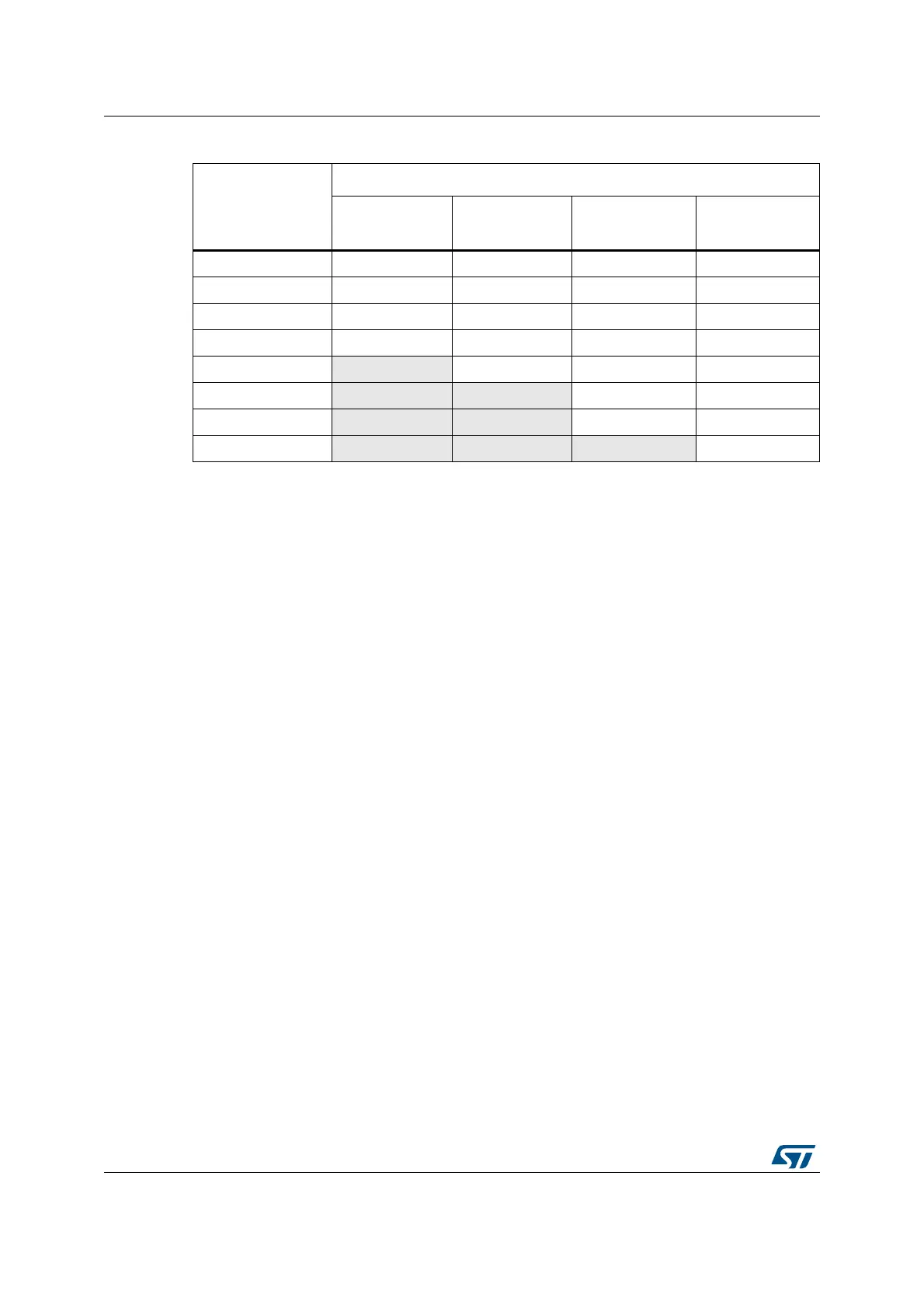
Table 3. Number of wait states according to Cortex
®
-M3 clock frequency
Wait states (WS)
(LATENCY)
HCLK - Cortex
®
-M3 clock frequency (MHz)
Voltage range
2.7 to 3.6 V
Voltage range
2.4 to 2.7 V
Voltage range
2.1 to 2.4 V
Voltage range
1.8
(1)
to 2.1 V
1. If IRROFF is set to VDD on STM32F20xx devices, this value can be lowered to 1.65 V when the device
operates in a reduced temperature range.
0 WS (1 CPU cycle) 0 < HCLK ≤ 30 0 < HCLK ≤ 24 0 < HCLK ≤ 18 0 < HCLK ≤ 16
1 WS (2 CPU cycles) 30 <HCLK ≤ 60 24 < HCLK≤ 48 18 < HCLK ≤ 36 16 < HCLK ≤ 32
2 WS (3 CPU cycles) 60 < HCLK ≤ 90 48 < HCLK ≤ 72 36 < HCLK ≤ 54 32 < HCLK ≤ 48
3 WS (4 CPU cycles) 90 < HCLK ≤ 120 72 < HCLK ≤ 96 54 < HCLK ≤ 72 48 < HCLK ≤ 64
4 WS (5 CPU cycles)
96 < HCLK ≤ 120 72 < HCLK ≤ 90 64 < HCLK ≤ 80
5 WS (6 CPU cycles)
90 < HCLK ≤ 108 80 < HCLK ≤ 96
6 WS (7 CPU cycles)
108 < HCLK ≤ 120 96 < HCLK ≤ 112
7 WS (8 CPU cycles)
112 < HCLK ≤ 120
 Loading...


