RM0033 Rev 9 521/1381
RM0033 Cryptographic processor (CRYP)
543
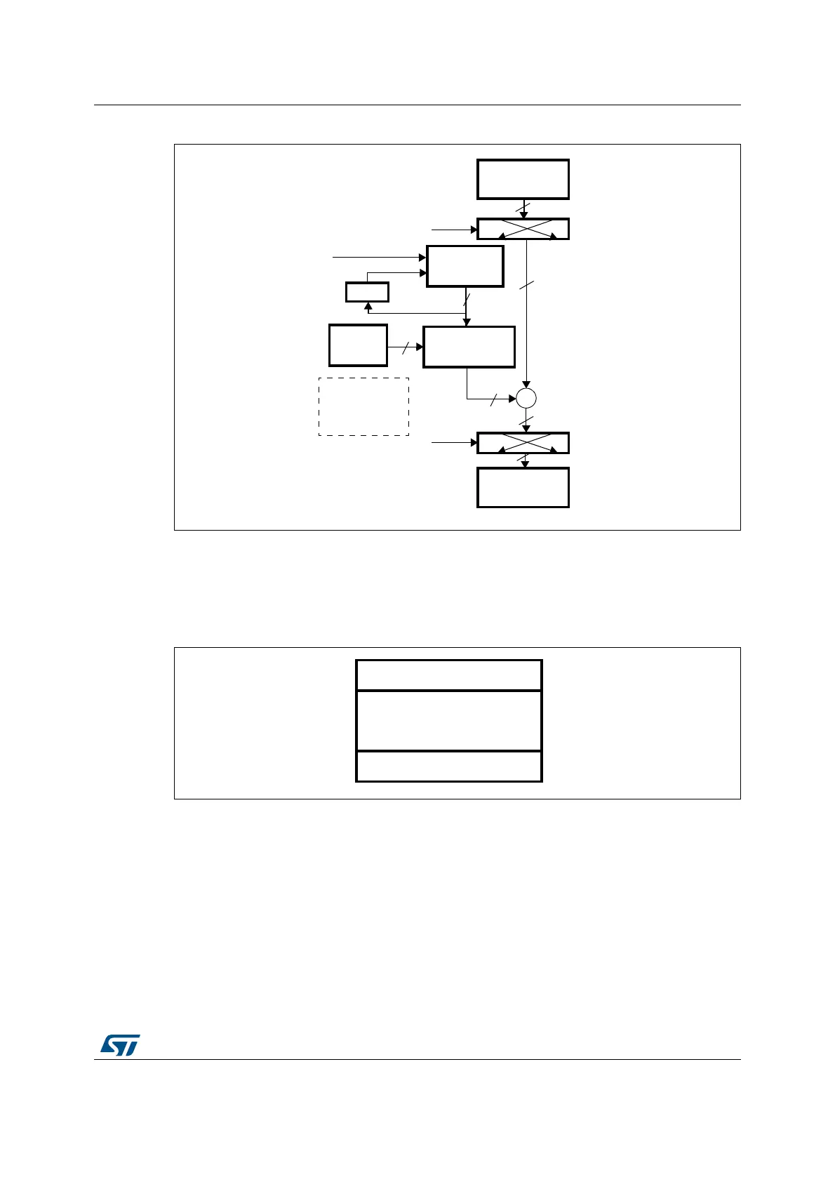
Figure 205. AES-CTR mode decryption
1. K: key; C: cipher text; I: input Block; o: output block; Ps: plain text before swapping (when decoding) or
after swapping (when encoding); Cs: cipher text after swapping (when decoding) or before swapping (when
encoding); P: plain text; IV: Initialization vectors.
Figure 206 shows the structure of the IV block as defined by the standard [2]. It is composed
of three distinct fields.
Figure 206. Initial counter block structure for the Counter mode
• Nonce is a 32-bit, single-use value. A new nonce should be assigned to each different
communication.
• The initialization vector (IV) is a 64-bit value and the standard specifies that the
encryptor must choose IV so as to ensure that a given value is used only once for a
given key
• The counter is a 32-bit big-endian integer that is incremented each time a block has
been encrypted. The initial value of the counter should be set to ‘1’.
The block increments the least significant 32 bits, while it leaves the other (most significant)
96 bits unchanged.
IN FIFO
AEA, encrypt
C, 128 bits
OUT FIFO
Ps, 128 bits
ciphertext P
plaintext C
swapping
+
IV0...1(L/R)
I, 128 bits
AHB2 data write
(before CRYP
is enabled)
(I + 1) is written
back into IV
at same time
than P is pushed
in OUT FIFO
swapping
P, 128 bits
DATATYPE
DATATYPE
K0...3
128, 192
or 256
Cs, 128 bits
+1
O, 128 bits
MS19025V1
Nonce 32 bits
Initialization vector (IV)
64 bits
Counter 32 bits
ai16074
 Loading...


