Chapter 9: CONNECTIONS
6. CONNECTION CABLE PIN ASSIGNMENT
9-32
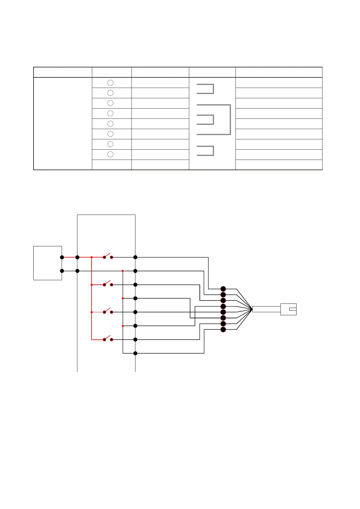
[VX-200SI's CTRL 1 – 4 terminals insulation]
The VX-200SI's CTRL 1 – 4 terminals can be insulated by performing settings to be externally powered. (Refer
to
p. 8-32 for the setting procedure.)
To VX-200SI CTRL IN
1 – 4
RJ45 connector
Pin No.
1
2
5
4
3
6
7
8
1
2
3
4
VX-200SI Control Input 1 – 4 (photocoupler-insulated)
Electrical characteristics
Voltage requirement: 17 – 24 V DC
Short circuit current: Under 10 mA
Control current: 4 – 5 mA
CTRL IN 1
COM 1
CTRL IN 2
COM 2
CTRL IN 3
COM 3
CTRL IN 4
COM 4
+
-
DC
17 – 24 V
External
power supply
•ConnectionexampleoftheVX-200SI'sCTRL1–4terminals
Note: For activating the VX-200SI, refer to
p. 9-27.
Connector Name RJ45 Pin No. Colour Pair Assignment
CTRL IN 1 – 4 Orange / white CTRL IN 1
Orange COM 1
Green / white CTRL IN 2
Blue COM 3
Blue / white CTRL IN 3
Green COM 2
Brown / white CTRL IN 4
Brown COM 4
Shield Shield NC
1
2
3
4
5
6
7
8