Chapter 9: CONNECTIONS
6. CONNECTION CABLE PIN ASSIGNMENT
9-31
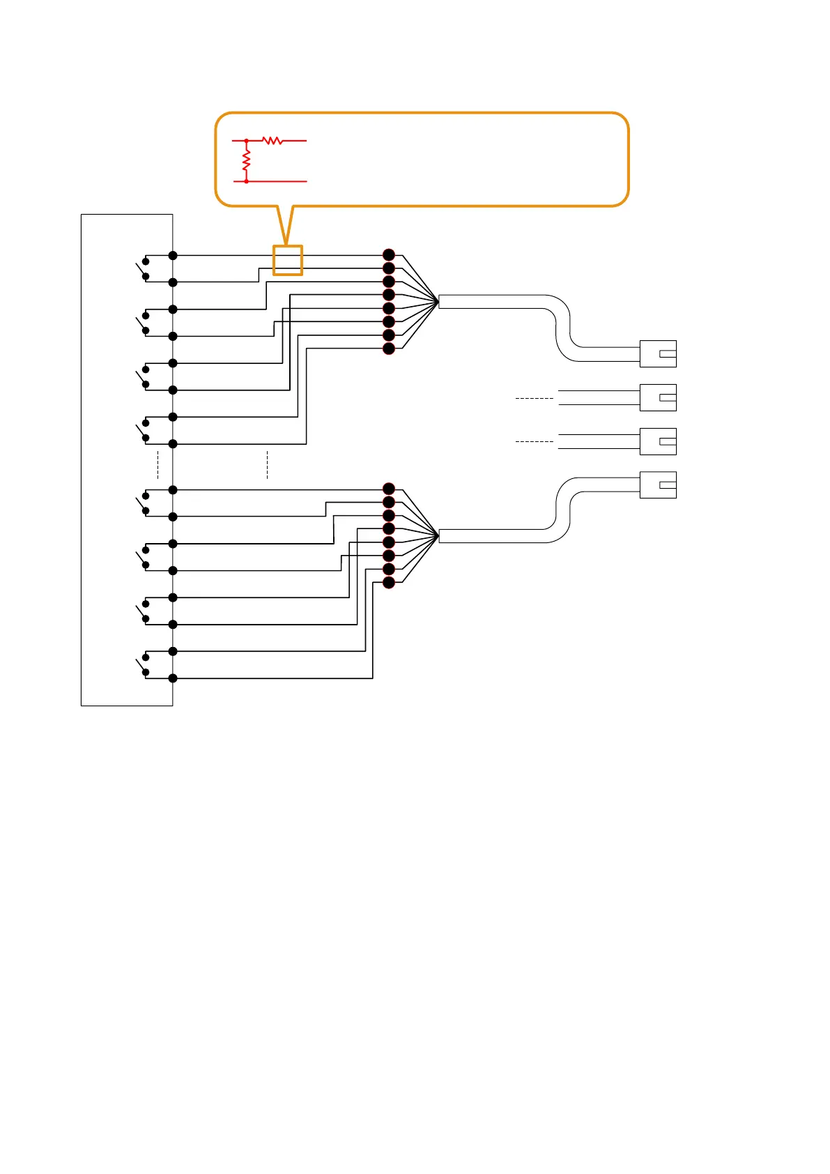
10 kΩ±5%
10 kΩ±5%
A wiring fault can be detected in the desired
control line by inserting the resistor network in
the line as shown on the left.
To VX-200SI CTRL IN
RJ45 connector
Pin No.
1
2
5
4
3
6
7
8
RJ45 connector
Pin No.
1
2
5
4
3
6
7
8
1 – 4
5 – 8
9 – 12
13 – 16
CTRL IN 1
COM 1
1
2
3
4
VX-200SI Control Input
Electrical characteristics
Open voltage: 24 V DC
Short circuit current: Under 10 mA
CTRL IN 2
COM 2
CTRL IN 3
COM 3
CTRL IN 4
COM 4
CTRL IN 13
COM 13
13
14
15
16
CTRL IN 14
COM 14
CTRL IN 15
COM 15
CTRL IN 16
COM 16
[VX-200SI connection example]
Note: For activating the VX-200SI, refer to p. 9-27.
[Control line surveillance]
Function for detecting a wiring fault in the cable connected to the external control output device can be set to
the control input terminals of the VX-200SI.
Connect the resistors to the cable of which fault is to be detected as shown above.
For the method of setting the fault detection function to the control input terminals, refer to
p. 7-15.
Notes
• ThewiringfaultdetectionfunctionwillnotworkontheCTRLINchannelsforwhich"Insulationsetting"has
been performed. (Refer to p. 8-32.)
• Besuretoconnecttheresistorsasshowninthediagramabove.
If no resistors are connected or resistors other than specified are used, the fault detection function will not
work correctly.
• Toassurestableoperationofthiswiringfaultdetection,itisrecommendedtouseashieldedtwistedpair
cable of 10 m or less.
• Besuretoconnecteachshieldwiretothefunctionalgroundterminalofeachdevice.