Arm
®
CoreLink™ GIC-600AE Generic Interrupt Controller
Technical Reference Manual
Document ID: 101206_0003_04_en
Issue: 04
Functional Safety
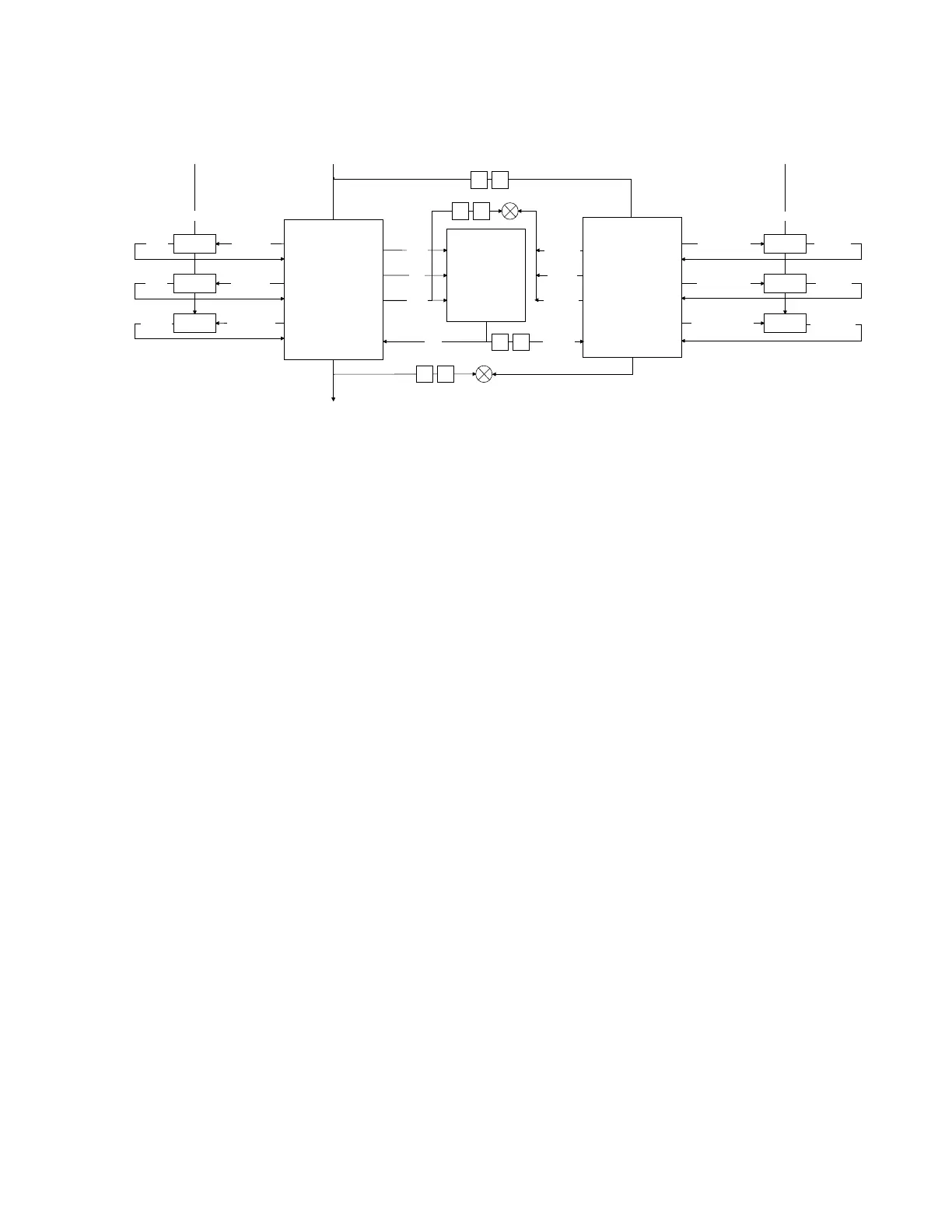
Figure 6-8: PPI lock-step
F
F
wdata
RAM
rdata
rdata_fdc
F
F
wakeup_ppsgi
wakeup_up
wakeup_dn
we/ce
addr
PPI_noram
checker
F
wdata_fdc
addr_fdc
we/ce_fdc
ClkGate
wakeup_ppsgi_fdc
wakeup_up_fdc
wakeup_dn_fdc
clk_dn_fdc
clk_up_fdc
clk_ppsgi_fdc
clk_fdc
ClkGate
ClkGate
The lock-step has a standard temporal delay of two cycles, with RAM sharing and comparators. A
circle with an X in the middle indicates a comparator. To save power, CRC is used to compress the
outputs.
The entire noram hierarchy is duplicated, with the comparators instanced in the block top level. The
clock gate and reset synchronizers are also duplicated in the top level.
The clocking is also duplicated. To provide redundancy in the reset and clock trees, the primary
(main) and checker (shadow) logic are clocked by a separate clock and separate reset. In the clock
tree, if a branch of the reset fails in the primary domain, then the checker domain detects the
failure. Similarly, if a branch of the reset fails in the checker domain, then the primary domain
detects the failure.
6.6.1 Comparators
The lockstep comparators consist of an XOR tree. The same parameterized comparator component
is instanced throughout the design to promote uniformity and allow the implementation to be
changed.
The comparators are known to be power hungry. Therefore, qualification is used wherever possible
so the comparators only check the outputs when necessary. For instance, an AXI bus comparator
checks the data only when the valid bits are asserted. This methodology is necessary to:
•
Prevent flagging on benign glitches when nothing is reading the bus.
•
Prevent a false error from being asserted due to unknown values on the bus, from RAMs, or
from uninitialized datapath flops.
Copyright © 2018–2020, 2022 Arm Limited (or its affiliates). All rights reserved.
Non-Confidential
Page 218 of 268