Arm
®
CoreLink™ GIC-600AE Generic Interrupt Controller
Technical Reference Manual
Document ID: 101206_0003_04_en
Issue: 04
Functional Safety
6.11 PPI and SPI interrupt interface protection
PPIs and SPIs are protected by _chk parity signal bits, which can be optionally added. A _chk signal
bit is added for each physical SPI and PPI signal rendered when setting the following parameters:
•
spi_wires
•
All PPI parameters that affect the number of PPI ports on the Redistributors
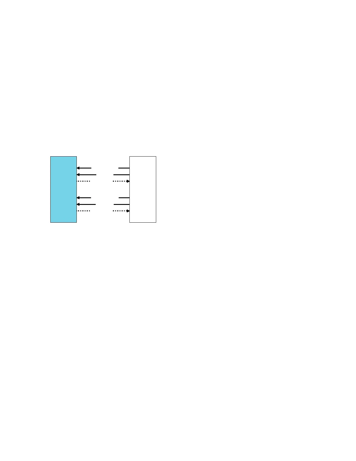
The following figure shows the signals that relate to PPI and SPI interrupt interface protection.
Figure 6-26: PPI and SPI interrupt interface protection
GIC
SoC
peripherals
n ≤ 16/core
m ≤ 960
ppi<n>_chk
ppi<n>
ppi<n>_r
spi_chk<m>
spi<m>
spi_r<m>
The _chk signal bits have inverse polarity from the ppi and spi signals that they protect. The ppi and
spi input signals and their corresponding _chk parity signal bit are considered asynchronous inputs.
The GIC-600AE contains specific logic to handle asynchronous uncertainty on the ppi/ppi_chk and
spi/spi_chk signal pairs.
6.11.1 PPI and SPI CHK bit timing
It is permissible for the chk signal bit to arrive on a different cycle than the ppi/spi signal bit that it
protects.
The SAF detector defines the upper limit of the allowed skew. If the SAF detector detects a
difference between the chk signal bit and the ppi/spi signal bit that it protects, it starts counting. If
it reaches the skew limit, the SAF detector assumes a SAF, and the GIC FMU flags the fault.
Clock Ratio (CR)
Equal to (GIC clock frequency)/(channel controller clock frequency)
Implementation skew
Silicon skew due to asynchronous clock domain crossings or other factors
Temporal delay skew
Skew between lock-step primary and redundant logic blocks
Copyright © 2018–2020, 2022 Arm Limited (or its affiliates). All rights reserved.
Non-Confidential
Page 244 of 268