Arm
®
CoreLink™ GIC-600AE Generic Interrupt Controller
Technical Reference Manual
Document ID: 101206_0003_04_en
Issue: 04
Signal descriptions
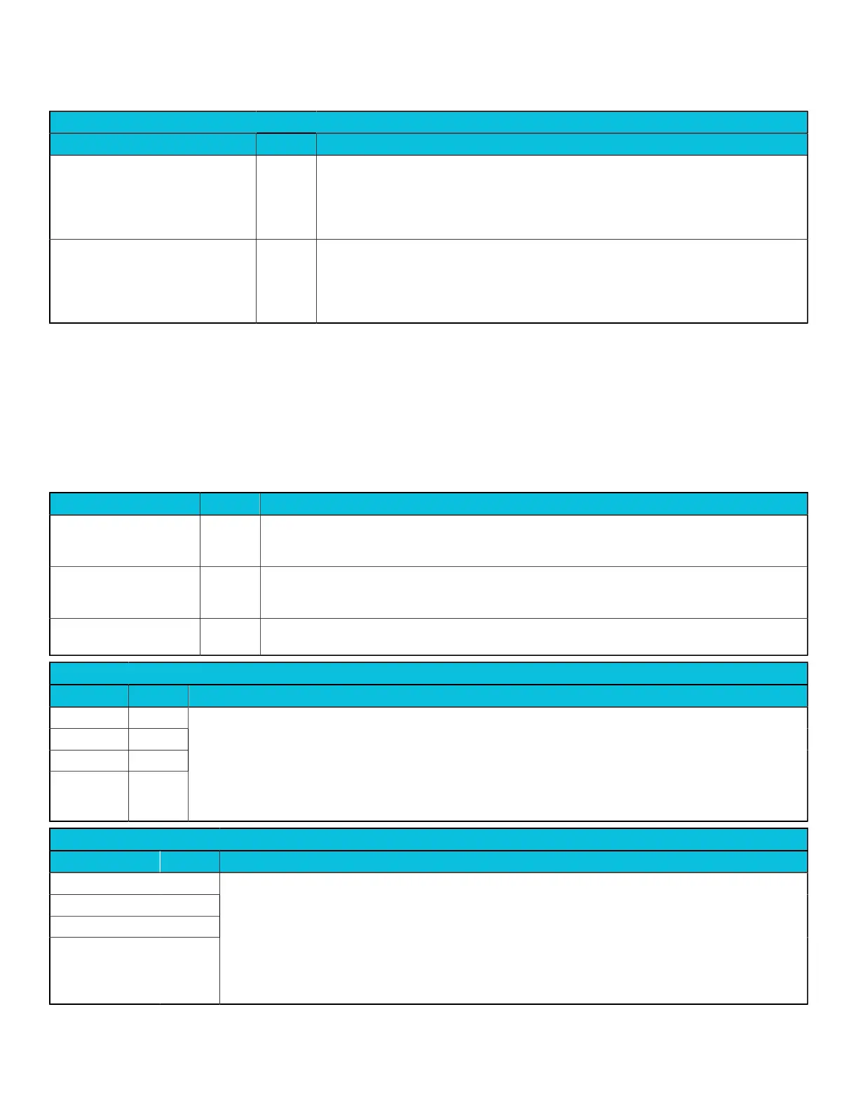
MBIST controller signals
Signal Direction Description
[<domain>_]mbistarray[variable:0]
13
Input Array selector.
This signal controls which RAM array is accessed. For the single RAM configuration, this
port is unused.
This signal is not present on a block containing only one RAM.
[<domain>_]mbistcfg Input MBIST ALLMODE enable.
When enabled, allows simultaneous access to all RAM arrays for maximum array power
consumption.
This signal is not present on a block containing only one RAM.
A.2 Power control signals
The following table shows the GIC-600AE power control signals.
Signal definitions
Table A-2: Power control signals
Signal Direction Description
cpu_active[_<ppi_block>]
[_<bus>][<cpus>−1:0]
Input Indicates if the core is active and not in a low-power state such as retention. This signal is used for
lowering the priority of selection for 1 of N SPIs. There is 1 bit per core on the ICC bus. See 4.6.2
Processor core power management on page 57.
wake_request[<cpus>
−1:0]
Output Wake Request signal to power controller indicating that an interrupt is targeting this core and it
must be woken. When asserted, the wake_request signal is sticky unless the Distributor is put into
the gated state.
wake_request_chk[<cpus>
−1:0]
Output Odd parity protection bits
SPI Collator Q-Channel device interface for power control
Signal Direction Description
qreqn_col Input
qacceptn_col Output
qdeny_col Output
qactive_col Output
Q-Channel device interface to flush out the path between the SPI Collator and the Distributor to aid in power
down.
When asserted, messages are not sent to the Distributor until low-power state is exited.
Note:
It is only safe to stop the SPI Collator clock if all interrupts are level sensitive, or if edge-triggered interrupts are
pulse extended into the SPI Collator.
ITS Q-Channel device interfaces for power control
Signal Direction Description
qreqn_its[<its>] Input
qacceptn_its[<its>] Output
qdeny_its[<its>] Output
qactive_its[<its>] Output
Required to flush out the path between the ITS and the Distributor.
There is one Q-Channel for each ITS.
All Distributor ITS Q-Channels are combined as a single set of vectored signals, qreqn_its[its_count−1:0].
The its_count parameter sets the number of ITS blocks on the chip.
These signals are not present in monolithic configurations where the Distributor and ITS share an ACE-Lite
port.
Copyright © 2018–2020, 2022 Arm Limited (or its affiliates). All rights reserved.
Non-Confidential
Page 251 of 268