Guide pins located at the rear of these modules help center locate the modules and reduce stress to the midplane
and module mounted connectors. Two captive screws (tool operated latches) are provided on the modules
face plate (chassis rear) to secure these modules into the chassis.
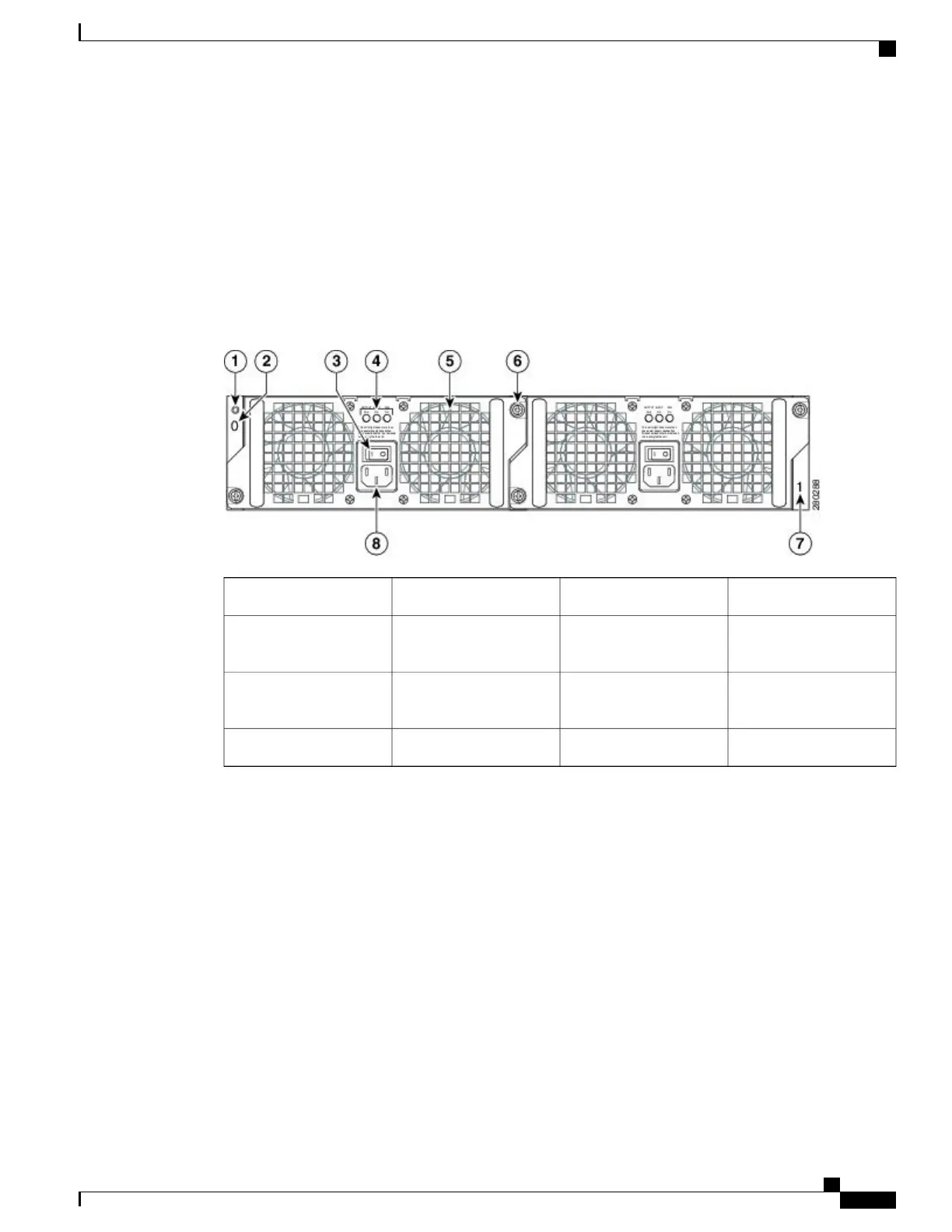
Cisco ASR 1002 AC Power Supply LEDs and Connector
The following figure shows the AC power supplies at the rear of the Cisco ASR 1002 Router. The Cisco ASR
1002 Router supports up to two power supplies.
Figure 16: Cisco ASR 1002 Router AC Power Supply
AC power supply fan5Chassis ESD socket1
AC power supply captive
installation screw
6AC power supply slot
number 0
2
AC power supply slot
number 1
7AC power supply On (|)
/Off (O) switch
3
AC power inlet8AC power supply LEDs4
The following table describes the power supply LEDs and connectors on the rear of the chassis.
Cisco ASR 1000 Series Router Hardware Installation Guide
67
Cisco ASR 1000 Series Routers Component Overview
Cisco ASR 1002 Router AC Power Supply
 Loading...


