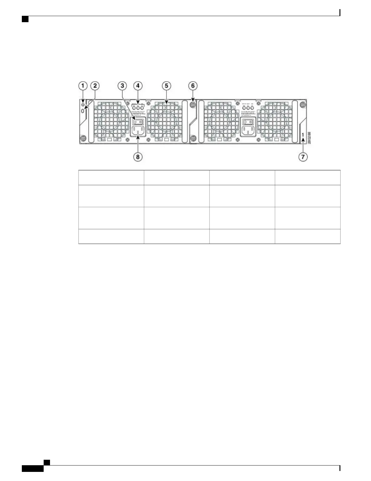
The following image shows the AC power supply for the Cisco ASR 1002-X Router.
Figure 148: AC Power Supply for the Cisco ASR 1002-X Router
AC power supply fan5Chassis ESD socket1
AC power supply captive
installation screw
6AC power supply slot
number 0
2
AC power supply slot
number 1
7AC power supply On (|)
/Off (O) switch
3
AC power supply inlet8AC power supply LEDs4
--48 VDC Power Supply for the Cisco ASR 1002-X Router
The –48 VDC power supply input connector is a Euro-style terminal block. It is compliant with safety agencies’
guidelines and electrical requirements of the supply. The DC power supply operates within specification from
–40.5 VDC to –72 VDC continuously after the power supply DC input is turned on a threshold of –43.5 V is
reached.
The –48 VDC power input connector accepts three wires: one positive polarity, one negative polarity, and
one ground (GND) wire. There are provisions on the front panel to wire tie and strain relief the DC input
wiring. The connection order is negative (–), positive (+), and GND. The DC power supply is secured into
the system chassis with two captive screws mounted on the faceplate.
Cisco ASR 1000 Series Router Hardware Installation Guide
324
Cisco ASR 1002-X Router Overview and Installation
Power Supplies in the Cisco ASR 1002-X Router
 Loading...


