Rear View
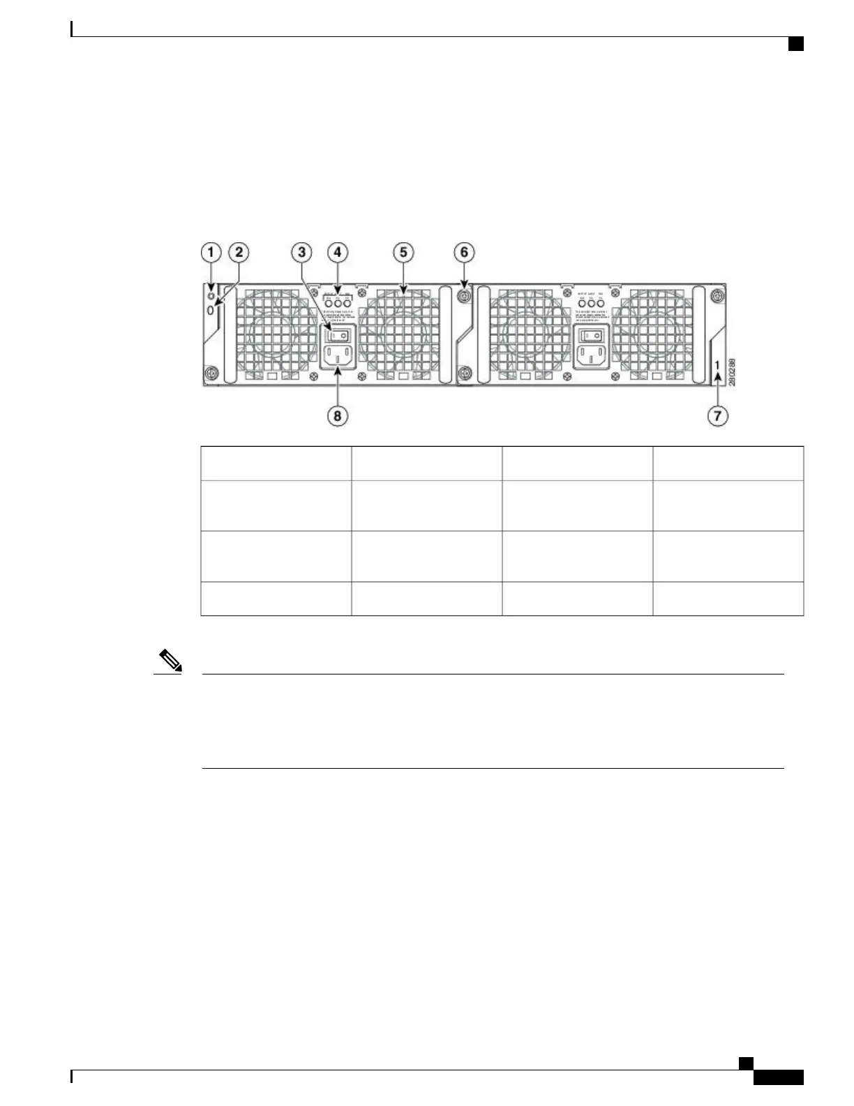
The following image shows the rear of the Cisco ASR 1002-F Router with AC power supplies installed.
Figure 116: Cisco ASR 1002-F Router With AC Power Supplies
—
Rear View
Fan5Chassis ESD socket1
Captive installation screw6AC power supply slot 0
label
2
AC power supply slot 1
label
7AC power supply On
(|)/Off (O) switch
3
AC power inlet8AC power supply LEDs4
On the side of the Cisco ASR 1002-F Router there is an eUSB panel door and the grounding lug as shown
in the “Cisco ASR 1002-F Router Chassis Ground Lug Location and eUSB Side Panel Door” figure in the
Attaching a Chassis Ground Connection section. This panel door must not be opened. There is a Do Not
Tamper label on the panel door. Do not remove the label. If there is a problem with the eUSB flash card,
then the chassis should be returned.
Note
Cisco ASR 1000 Series Router Hardware Installation Guide
277
Cisco ASR 1002-F Router Overview and Installation
Rear View
 Loading...


