Connecting DC Input Power to Cisco ASR 1013 Router
This section describes how to connect the DC power supply into the Cisco ASR 1013 Router. The following
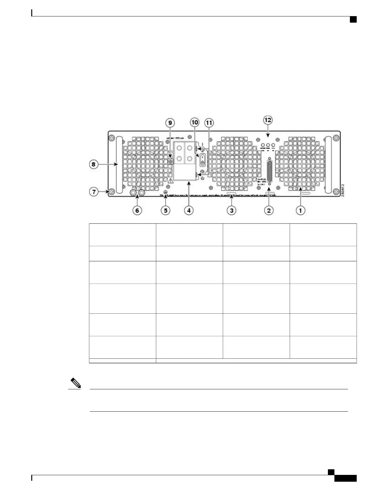
image shows the Cisco ASR 1013 Router DC power supply and labels.
Figure 190: Cisco ASR 1013 Router DC Power Supply
DC power supply captive
screw
7Fan1
DC power supply handle8DB-25 alarm connector*2
Terminal block and
plastic cover single screw
9Tie-wrap tab3
On/Off (|/O) circuit
breaker switch
10DC power supply
terminal block and plastic
cover
4
Terminal block and
plastic cover slot tab
11Ground symbol5
Power supply LEDs12DC power supply ground
studs
6
Shielded cables must be used to connect to the DB-25 alarm connector on both the AC and DC power
supplies, in order to comply with FCC/EN55022/CISPR22 Class A emissions requirements.
Note
Before you begin to install the DC power supply into the Cisco ASR 1013 Router, read these important notices:
Cisco ASR 1000 Series Router Hardware Installation Guide
397
Cisco ASR 1013 Router Overview and Installation
Connecting DC Input Power to Cisco ASR 1013 Router
 Loading...


