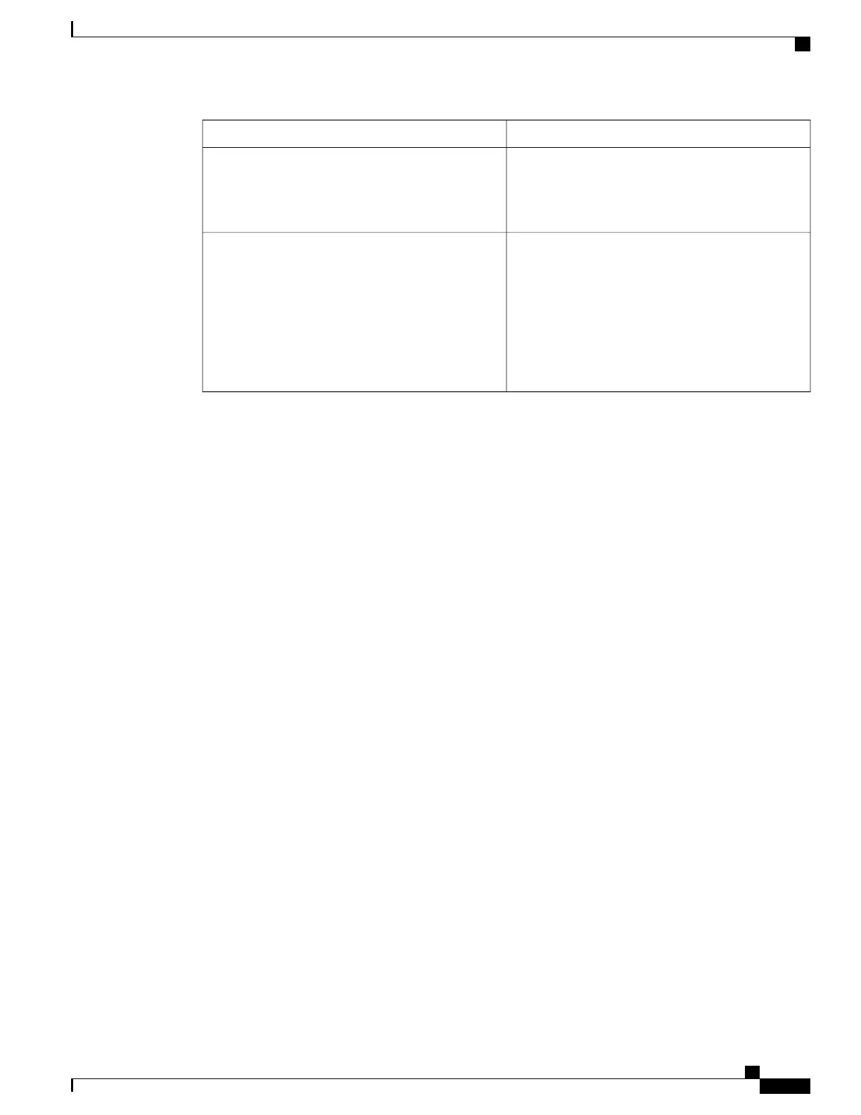
Corrective ActionSymptom
If your system has power, check the STATUS LED
on the ASR 1000 Series route processor and make
certain all connections are secure. See Table 2-8 for
more information about the LEDs.
System fails to boot up properly
If the two power supplies are both showing GREEN
on their Output LEDs, then a failure of one power
supply will not result in a system failure.
Only one operating power supply is required for the
Cisco ASR 1000 Series Router system to operate.
Having only one supply powered is a supported
configuration. If both supplies have an OUTPUT
FAIL LED red, then the system will fail.
Power problems
Troubleshooting Using a Subsystem Approach
To solve a system problem, try to isolate the problem to a specific subsystem. Compare current router behavior
with expected router behavior. Because a startup issue is usually attributable to one component, it is most
efficient to examine each subsystem, rather than trying to troubleshoot each router component.
For troubleshooting purposes in this chapter, the router consists of the following subsystems:
• Power subsystem—Includes the following components:
AC input or DC input power supplies, also called power entry modules (PEMs).
• Processor subsystem—The Cisco ASR 1000 series RP, ESPs, and SIPs have onboard processors. The
RP downloads software to each board in the system over the Ethernet Out of Band Channel (EOBC).
There is a status LED on each board (RP, ESP, SIP) that indicates the progress of loading software. Note
that on routers such as the Cisco ASR 1001 Router and the Cisco ASR 1002-X Router that have an
integrated route processor, embedded services processor, and SIP, there is a single status LED to show
the loading status of the system. The LED is red if ROMMON does not boot. If the board has booted
ROMMON successfully, the LED is yellow. If operation software (IOS) has downloaded successfully,
the LED is green.
• Cooling subsystem—Consists of three fans in each of the Cisco ASR 1006 Router and Cisco ASR 1004
Router power supplies and two fans in each of the Cisco ASR 1002 Router, Cisco ASR 1002-F Router,
and Cisco ASR 1002-X Router power supplies. On the Cisco ASR 1001 Router, each PEM has its own
fan and the system itself has a separate fan tray. The fans draw in air from each of the chassis and PEMs
in a front to back direction.
Normal Router Startup Sequence
You can generally determine when and where the power supply failed during the startup sequence by checking
the status LEDs on the power supply modules.
In a normal router startup sequence, the following sequence of events and conditions occur:
Cisco ASR 1000 Series Router Hardware Installation Guide
647
Troubleshooting Initial Startup Problems
Troubleshooting Using a Subsystem Approach
 Loading...


