DescriptionColorLEDLED Label
If the INPUT OK LED is
illuminated, this LED is red if
the DC output voltages are
below the minimum limit or
above the maximum limit.
If the INPUT OK LED is not
illuminated, this LED might be
off or red.
RedPower supply activityOUTPUT FAIL
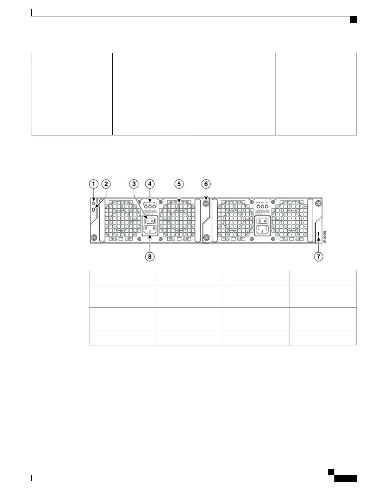
The following image shows the AC Power Supply for the Cisco ASR 1002 Router.
Figure 84: AC Power Supply for the Cisco ASR 1002 Router
AC power supply fan5Chassis ESD socket1
AC power supply captive
installation screw
6AC power supply slot
number 0
2
AC power supply slot
number 1
7AC power supply On (|)
/Off (O) switch
3
AC power supply inlet8AC power supply LEDs4
48 VDC Power Supply for Cisco ASR 1002 Router
The –48 VDC power supply input connector is a Euro-style terminal block. It is compliant with safety agencies’
guidelines and electrical requirements of the supply. The DC power supply operates within specification from
–40.5VDC to –72VDC continuously once the power supply DC input turn on threshold of –43.5 V has been
reached.
The –48 VDC power input connector Euro-style terminal block will accept three wires: one positive polarity,
one negative polarity, and one ground wire. There are provisions on the front panel to wire tie and strain relief
Cisco ASR 1000 Series Router Hardware Installation Guide
227
Cisco ASR 1002 Router Overview and Installation
Power Supplies in the Cisco ASR 1002 Router
 Loading...


