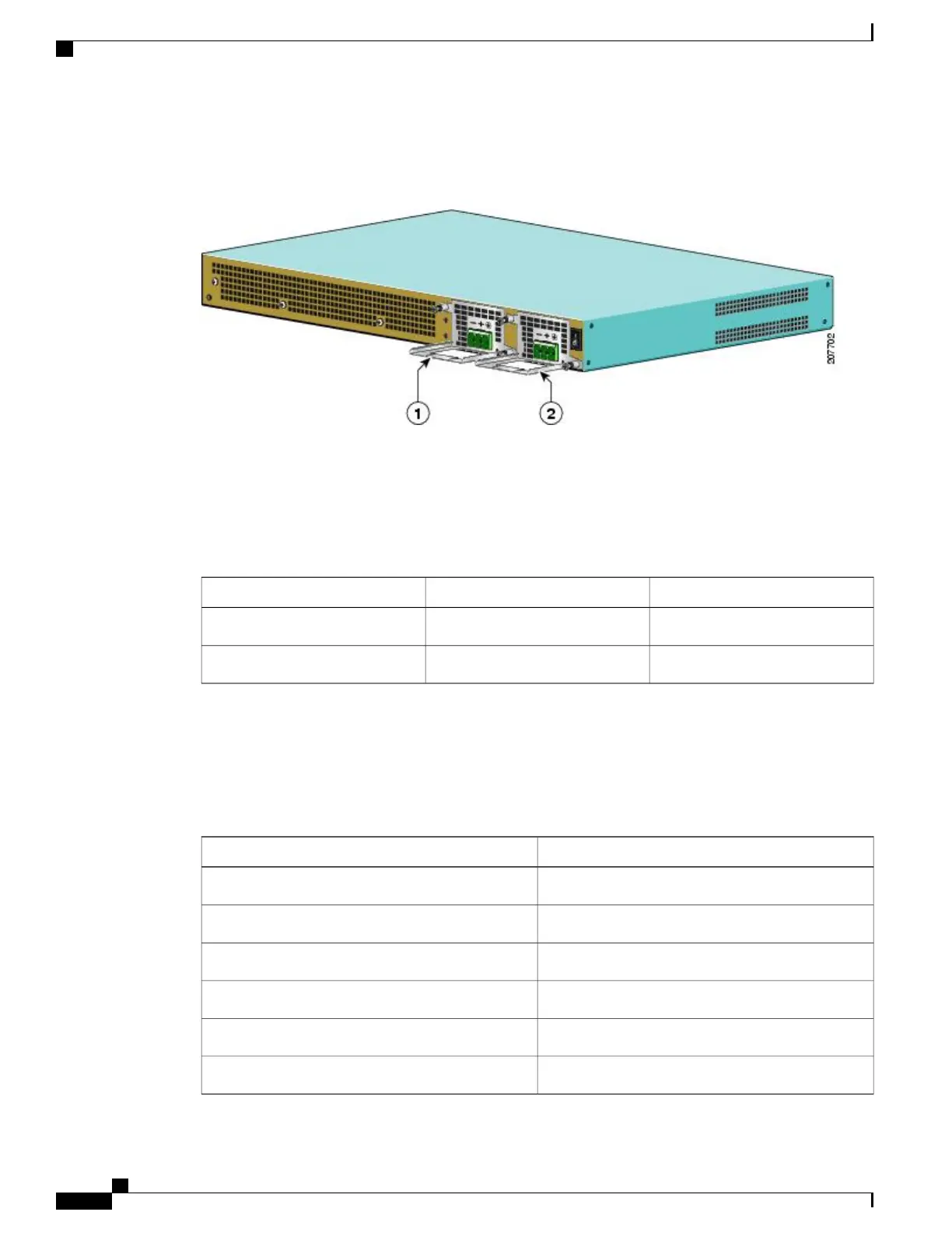
The following image shows the –48 VDC power supplies for the Cisco ASR 1001 Router.
Figure 206:
–
48 VDC Power Supply for the Cisco ASR 1001 Router
The output voltage alarm is declared when the output voltage is below the low end of the minimum or above
the high end of the maximum limits. When the output voltage is above the high end of the minimum or below
the low end of the maximum limits, the red state will not be activated.
The following table shows the –48 VDC power supply output voltage alarm ranges.
Table 85:
–
48 VDC Power Supply Output Voltage Alarm Threshold Ranges
MaximumMinimumOutput
12.8-13.8V10.0-11.2V12V
None2.6 - 3.0 V3.3V
Power Cords Supported by the Cisco ASR 1001 Router
The following table lists the power cords that are supported by the Cisco ASR 1001 Router.
Table 86: Power Cords Supported by the Cisco ASR 1001 Router
DescriptionPower Cord Item Number
AC Power Cable ANSI 220VAC Right Exit15454-M-ACCBL-R2
Power Cord, 110 V, Right AngleCAB-AC-RA
Plug, Power Cord, Australian, 10 A, Right AngleCAB-ACA-RA
Power Cord China, Right AngleCAB-ACC-RA
Power Cord Europe, Right AngleCAB-ACE-RA
Power Cord, Italian, Right AngleCAB-ACI-RA
Cisco ASR 1000 Series Router Hardware Installation Guide
424
Cisco ASR 1001 Router Overview and Installation
Power Supplies in the Cisco ASR 1001 Router
 Loading...


