DescriptionDirectionSignalPin
Data Set Ready/Data
Carrier Detect
InputDSR/DCD7
Clear to SendInputCTS8
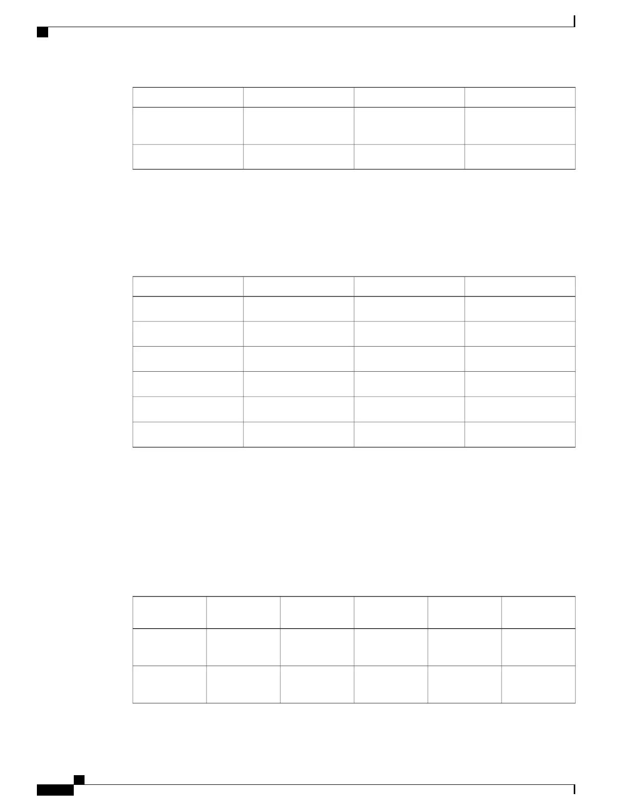
Cisco ASR 1004 Router BITS Port Signals and Pinouts
The following table lists the pinouts of the front panel Building Integrated Timing Supply (BITS) RJ45 port.
Table 108: BITS RJ-45 Receptacle Pinouts for Cisco ASR 1004 Router
DescriptionDirectionSignalPin
Receive RingInputRX Ring1
Receive TIP (T1/E1)InputRX TIP2
——
N/C3, 4
—
UnusedTX Ring5
—
UnusedTX TIP6
——
N/C7,8
Cisco ASR 1004 Router DB-25 Pinout Assignments for Alarm Relays
The following table lists the common, normally open, and normally closed relay contacts accessible to an
external alarm monitoring facility by means of the DB-25 connector.
For more information about the DB-25 alarm connector, see Cisco ASR 1006 Router DB-25 Pinout Assignments
for Alarm Relays, on page 620.
Table 109: Cisco ASR 1004 Router DB-25 Alarm Connector Pinout Assignments
SPARENormally Closed
(NC)
Normally Open
(NO)
Common
(CM)
DescriptionSignal
—
1412Critical Audible
Alarm
CRTAA
—
15316Major Audible
Alarm
MAJAA
Cisco ASR 1000 Series Router Hardware Installation Guide
624
Cisco ASR 1000 Series Router Specifications
Cisco ASR 1004 Router BITS Port Signals and Pinouts
 Loading...


