AUX—One RS-232
auxiliary port
3
MGMT—One RJ-45
10/100/1000 management
Ethernet port
1
——CON—One RS-232
console port
2
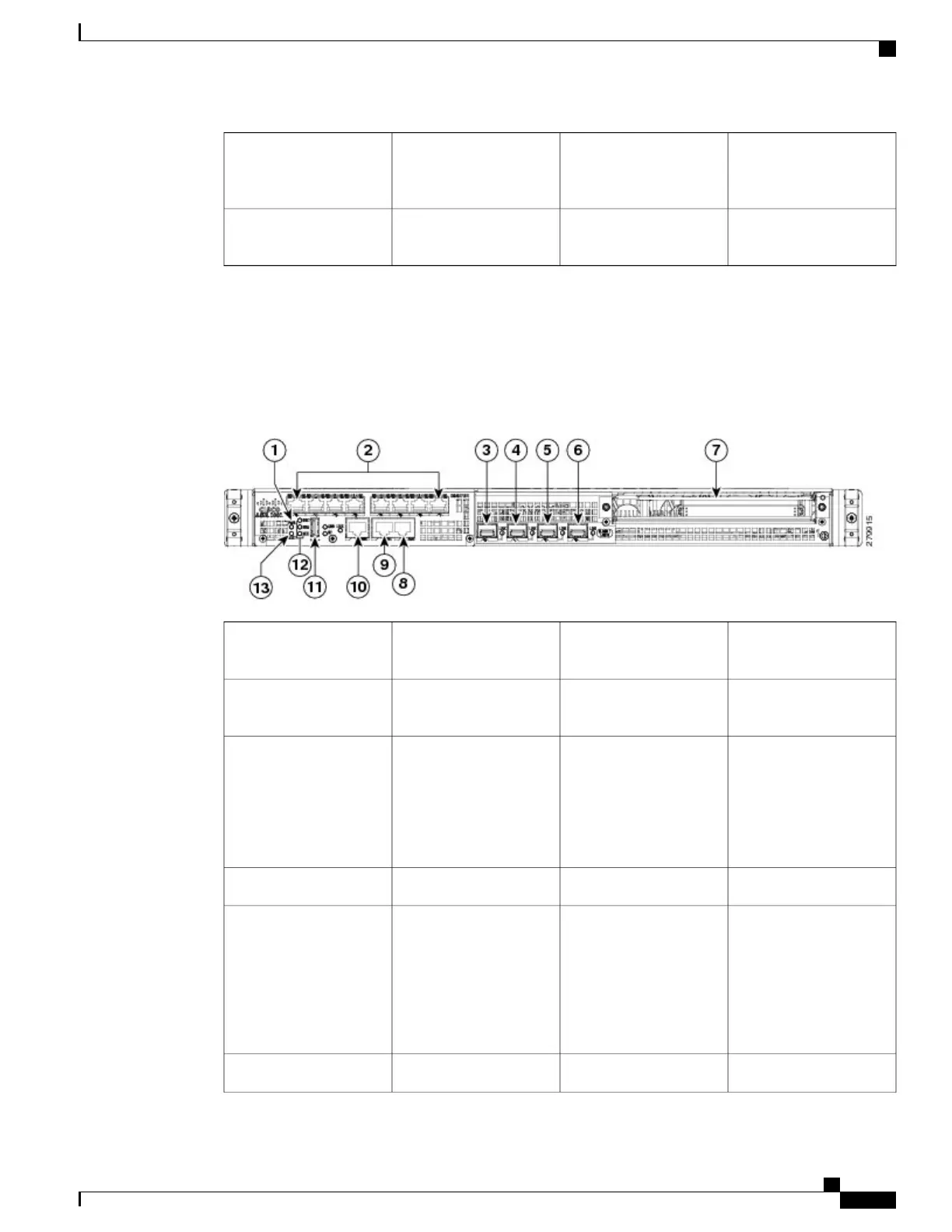
Cisco ASR 1001 Chassis Front View
The following image shows the front of the Cisco ASR 1001 Router.
Figure 203: Cisco ASR 1001 Router Front View
AUX—one RS-232
auxiliary port
8
PWR—Power LED
1
CON—one RS-232
console port
9Integrated daughter card
I/O space
2
MGMT —one RJ-45
10/100/1000 management
Ethernet port
10
GE 2/0 and 0/0—The
built-in GE ports use
industry standard
front-panel removable
SFP optics and SFP
copper interfaces.
3
USB port11GE 2/1 and 0/14
CRIT LED—critical
alarm indicator
MAJ LED—major alarm
indicator
MIN LED —minor alarm
indicator
12GE 2/2 and 0/25
STAT—status LED
13GE 2/3 and 0/36
Cisco ASR 1000 Series Router Hardware Installation Guide
417
Cisco ASR 1001 Router Overview and Installation
Cisco ASR 1001 Chassis Front View
 Loading...


