DescriptionColorLEDLED Label
When the LED is off, it signals
that the –48 VDC output
voltage are within the normal
operating range. Output voltage
between the minimum and
maximum limits will not create
an output fail alarm, and output
voltages below the minimum or
above the maximum will create
an Output Fail alarm.
When you turn the power
supply on, the red LED
illuminates for two to three
seconds to test LED operation
before going off.
RedPower supply activityOUTPUT FAIL
AC/DC Power System Output for Cisco ASR 1013
The power supply output tolerance is defined in the following table under all combinations of line variation.
Total system consumption per power supply should not exceed 1600 W.
The output tolerance values shown in this table apply to the ASR1013/06-PWR-DC and
ASR1013/06-PWR-AC power supplies. The Cisco ASR 1013 Router and the Cisco ASR 1006 Router
support these power supplies.
Note
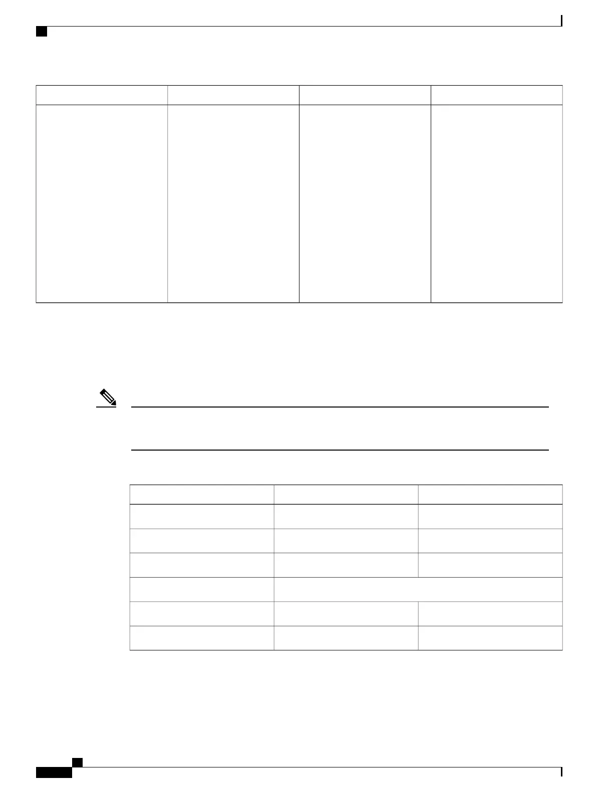
Table 34: Cisco ASR 1013 Router Power System Output Voltage and Output Current
+3.3 V+12 VDCOutput Voltage
3.20 VDC11.80 VDCMinimum
3.30 VDC12.00 VDCNominal
3.40 VDC12.20 VDCMaximum
Output Current
0 A0 AMinimum
3.125 A136 AMaximum
Cisco ASR 1000 Series Router Hardware Installation Guide
82
Cisco ASR 1000 Series Routers Component Overview
–48 VDC Power Supply LEDs and Connectors for Cisco ASR 1013
 Loading...


