DC power supply captive
screw
7Fan1
DC power supply handle8DB-25 alarm connector*2
Terminal block and
plastic cover single screw
9Tie-wrap tab3
On/Off (|/O) circuit
breaker switch
10DC power supply
terminal block and plastic
cover
4
Terminal block and
plastic cover slot tab
11Ground symbol5
Power supply LEDs12DC power supply ground
studs
6
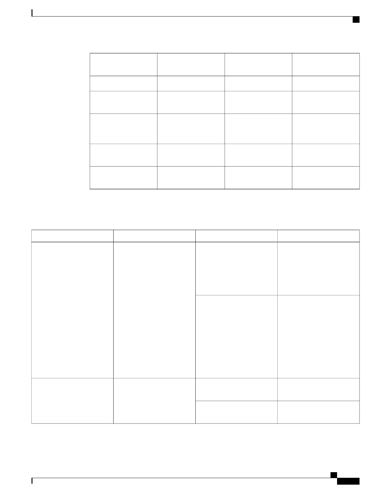
The following table describes the power supply LEDs and connectors on the rear of the chassis.
Table 33: Cisco ASR 1013 Router
–
48 VDC Power Supply LEDs
DescriptionColorLEDLED Label
LED illuminates green to signal
that the –48 VDC power supply
input voltage is greater
than–43.5VDC at turn-on and
remains green down to
–39VDC.
GreenA bi-color LED indicates input
voltage
INPUT OK
The LED illuminates amber
when the input voltage (falls
below –39VDC) and indicates
that there is still a voltage
present (voltage on the terminal
block). The LED remains amber
and is active to around 25 V
+/-5 V. The LED is not
illuminated if the input is below
–15 V input.
Amber
The LED illuminates s green
when all fans are operational.
GreenA bi-color LED indicates power
supply fan status
FAN OK
The LED illuminates red when
a fan failure is detected.
Red
Cisco ASR 1000 Series Router Hardware Installation Guide
81
Cisco ASR 1000 Series Routers Component Overview
–48 VDC Power Supply LEDs and Connectors for Cisco ASR 1013
 Loading...


