DETAILED STEPS
Step 1
Ensure that the chassis ground is connected on the chassis before you begin installing the DC power supply, as described
in the Attaching a Chassis Ground Connection, on page 438.
Step 2
At the rear of the chassis, next to the power supply bay PS1, ensure that the power supply switch is in Standby position.
Step 3
Turn off the circuit breaker to the power supply.
Wiring the DC Input Power Source
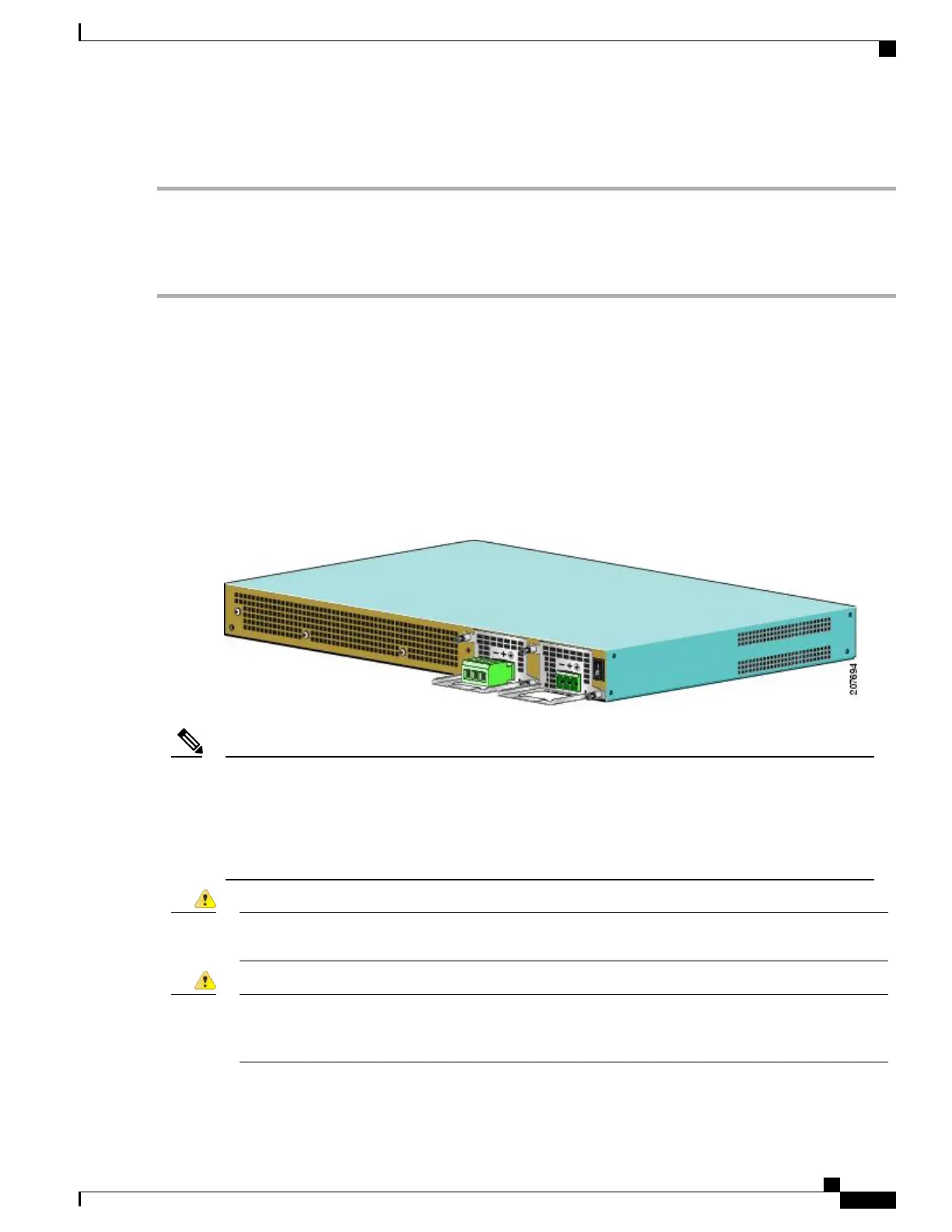
The Cisco ASR 1001 Router DC power supply has a connector plug that is installed into the power supply
terminal block header. The following figure shows a view of a DC power supply with a DC connector plug
inserted (no wires installed) into the power supply block header in power supply PS0 (on the left), and the
other power supply with no connector plug inserted into power supply PS1 (on the right).
Figure 221: Cisco ASR 1001 Router DC Power Supply Terminal Block With a Connector Plug in Slot 0 and Without a
Connector Plug in Slot 1
Two types of DC connector plugs are supported for use with the DC power supply for the Cisco ASR
1001 Router. In one type of connector plug, the screw holes are raised above the connector plug body. In
the second type, the screw holes are not raised above the connector plug body. The figure in step 6 shows
the connector plug in which the screw holes are not raised. The only difference in the method for using
these two types of connector plugs is related to the wire-strip length, which is mentioned later in this
section.
Note
When installing or replacing the unit, the ground connection must always be made first and disconnected
last. Statement 1046
Danger
This product relies on the building’s installation for short-circuit (overcurrent) protection. Ensure that the
protective device is rated not greater than: 120 VAC, 20A U.S. (240 VAC, 10A international). Statement
1005
Danger
Cisco ASR 1000 Series Router Hardware Installation Guide
453
Cisco ASR 1001 Router Overview and Installation
Installing DC Input Power on the Cisco ASR 1001 Router
 Loading...


