The +24 VDC power supply product is labeled at +27 VDC input because the typical battery float voltage
is +27V; but generically, these power systems can be labeled +24 V and referred to as +24 VDC (see the
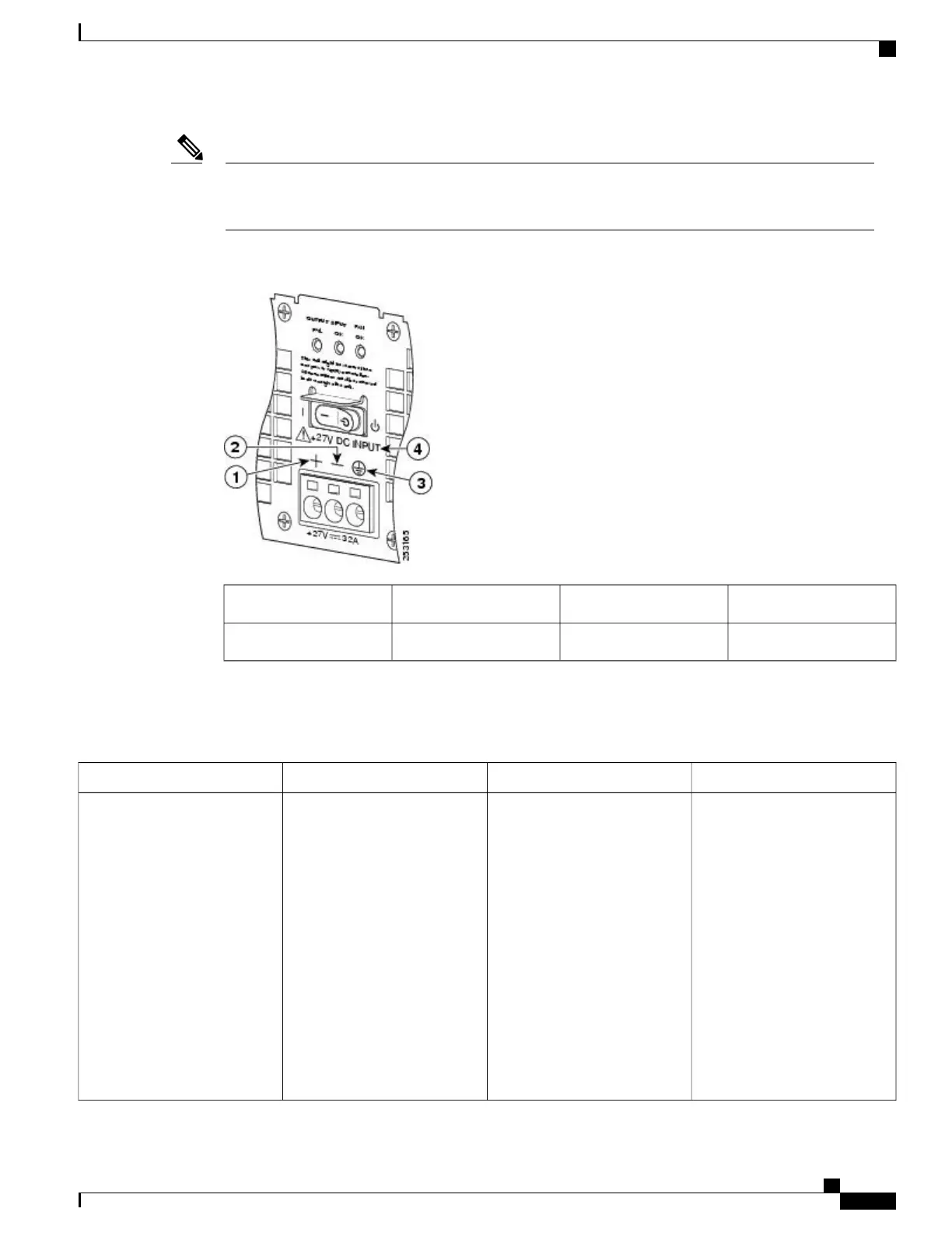
following figure for more information).
Note
Figure 19: Cisco ASR 1002 Router Rear View With +24 VDC Power Supply Terminal Block
GROUND (GND) LEAD6Positive (+) lead1
+27VDC label7Negative (-) lead2
The following table describes the power supply LEDs and connectors on the rear of the chassis.
Table 29: Cisco ASR 1002 Router +24 VDC Power Supply LEDs
DescriptionColorLEDLED Label
When the LED is off, it signals
that the +24 VDC output
voltage are within the normal
operating range. Output voltage
between the minimum and
maximum limits will not create
an output fail alarm, and output
voltages below the minimum or
above the maximum will create
an Output Fail alarm.
When you turn the power
supply on, the red LED
illuminates for two to three
seconds to test LED operation
before going off.
RedPower supply activityOUTPUT FAIL
Cisco ASR 1000 Series Router Hardware Installation Guide
73
Cisco ASR 1000 Series Routers Component Overview
Cisco ASR 1002 Router +24 VDC Power Supply
 Loading...


