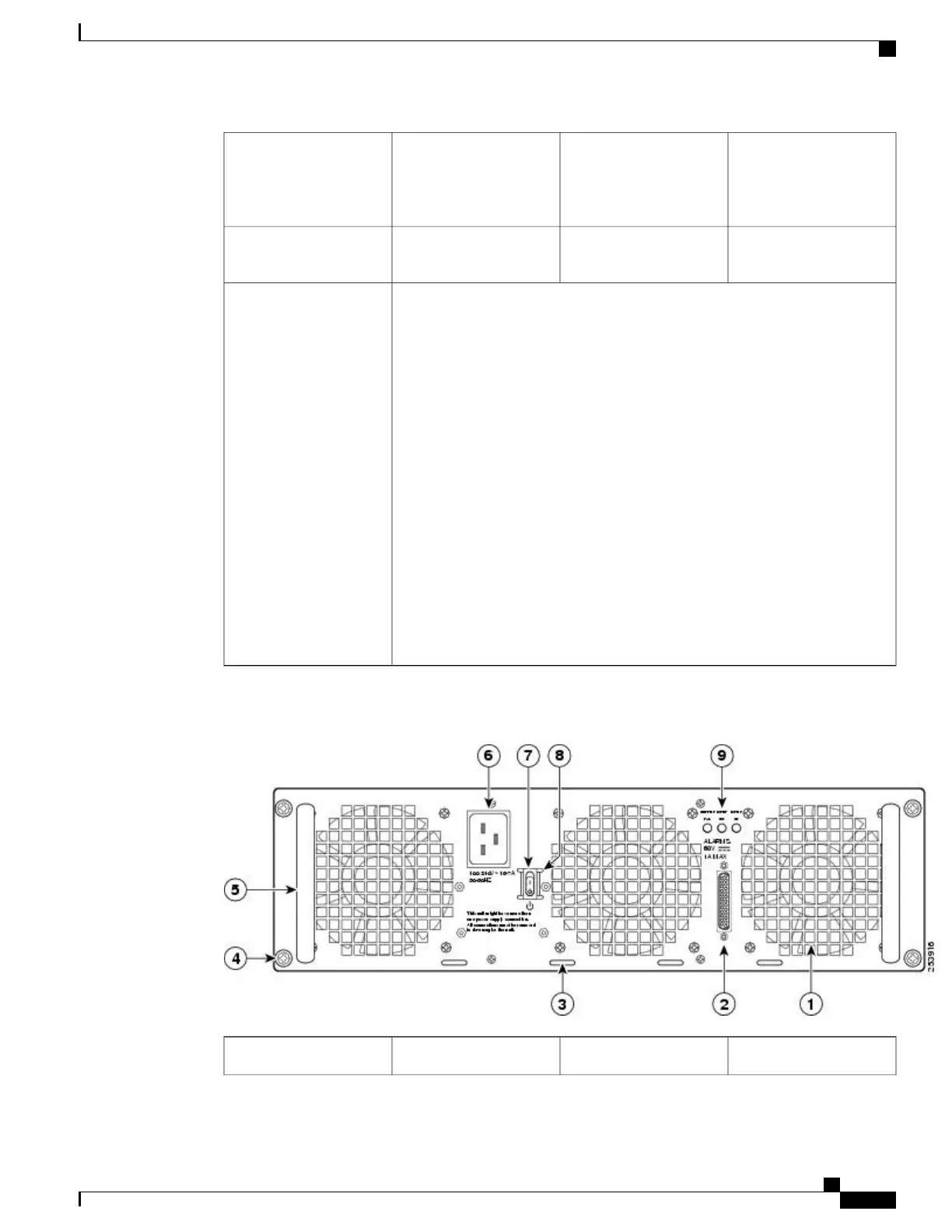
AC power supply
Standby switch. A
Standby switch is not
considered a disconnect.
7Cable tie-wrap tabs3
AC power supply LEDs8AC power supply captive
screws
4
*For information about
the DB-25 alarm
connector, how it works,
and Cisco ASR 1000
series route processor
LEDs, see xref “How
Cisco ASR1000-RP
Alarm Monitoring
Works” section on page
2-20.
Note: Shielded cables
must be used to connect
to the DB-25 alarm
connector on both the AC
and DC power supplies,
in order to comply with
FCC/EN55022/CISPR22
Class A emissions
requirements.
The following figure shows the ASR1013/06-PWR-AC power supply of the Cisco ASR 1006 Router.
AC power inlet6AC power supply fan1
Cisco ASR 1000 Series Router Hardware Installation Guide
541
Removing and Replacing FRUs from the Cisco ASR 1000 Series Routers
Removing and Replacing a AC Power Supply in Cisco ASR 1006 Router
 Loading...


