Ergonomic Recommendations
Product Reference Guide
31
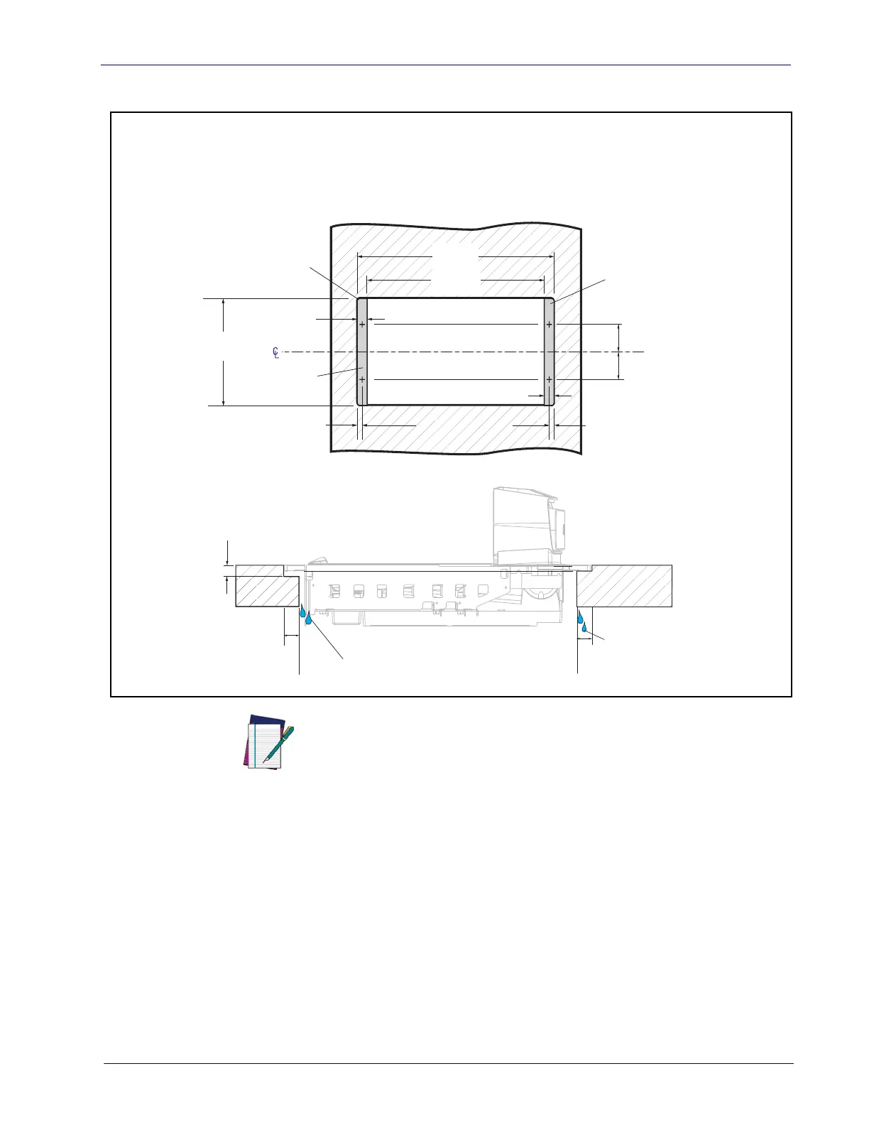
Figure 15. Counter Cutout and Scanner Support Dimensions - Long
3. Drill any holes required to install the AC/DC Power Supply, the Remote
Scale Display cable and the interface cable(s) observing the following:
• Interface cables (and display cable, if applicable) should be routed away
from all highly inductive electrical devices, like motors and conveyor
belts, and even away from the unit’s power cable if possible. See also
"Recommended Power Installation" on page 21.
• Cables should be easy to remove in the event that replacement is
required. A little planning now will save a lot of frustration later. See also
"Service Access Requirements" on page 21.
51.12cm
(20.13")
1.91cm
(0.75")
47.31cm
(18.63")
Flange Support
Flange Support
1.91cm
(0.75")
Max. Radius = 0.64cm
(0.25") 4x
0.95cm
(0.38")
0.95cm
(0.38")
7.77cm
(3.06")
7.77cm
(3.06")
29.53cm
(11.63")
Models 9805 and 9806
LONG (FLANGE MOUNT)
3.8 cm
(1.5")
1.9 cm
(0.75")
1.9 cm
(0.75")
0.95 cm
(0.38")
Liquid
Drainage
Liquid Drainage
If leveling feet are needed for models
93/9405 and 93/9406, place in the
locations marked with plus signs (+).
COUNTER CUTOUT DIMENSIONS
NOTE
If you plan to use a router on a countertop with a thickness of 1.9 cm
(0.75”) plywood, you’ll need to add a backing strip that supports the
area routed out for the support flanges (see
Figure 12). This sup-
port strip should minimally be made of 1.9 cm (0.75”) thick plywood
and be approximately 10.2 cm (4.0”) wide and 35.6 cm (14.0”) long.
This strip should be glued as well as screwed to the underside of the
countertop.

 Loading...