Ergonomic Recommendations
Product Reference Guide
37
3. Powerup & Operational Verification
Connect the power cable first at the scanner, then at the AC outlet.
1. Plug your scanner into an electrical outlet that has been wired to meet all
applicable electrical codes, laws, and regulations and has a common
ground with the Point-of-Sale terminal.
2. When power is applied to the unit, the normal indicator sequence is:
• The good read indicator LEDs will be lit (dim) steadily.
• [EAS models ONLY] The EAS indicator LED will flash ON/OFF during
power-up.
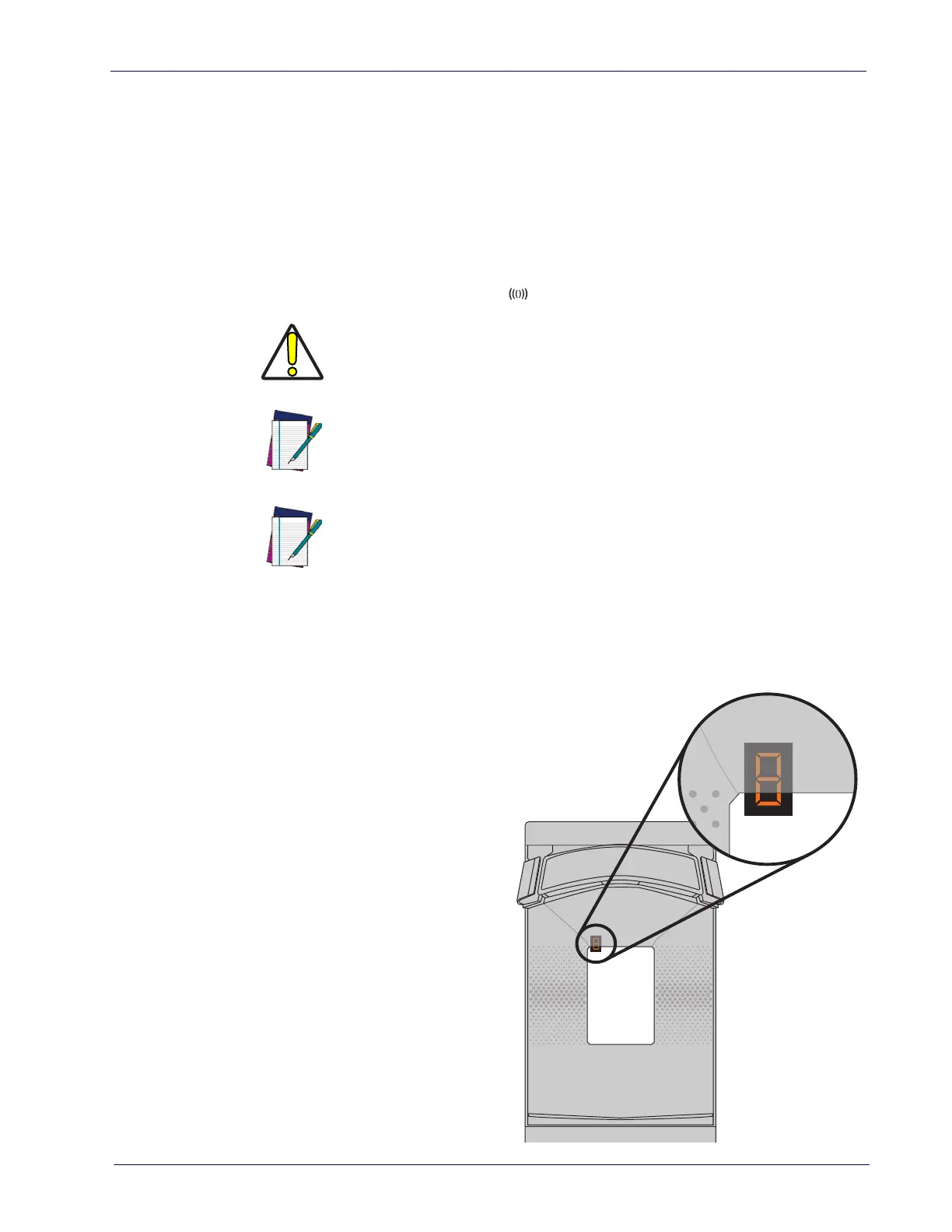
Figure 21. Health & Status Indicator
CAUTION
If the Selftest detects a problem, the Health & Status Indicator will
display a number code. Refer to
Chapter 5. Problem Isolation, for
a description of failure codes and problem isolation procedures.
NOTE
On rare occasions, performance of scale calibration may be neces-
sary to obtain a zero reading on the display.
NOTE
If the Remote Scale Display is not connected, a scanner power-up
Selftest will sound a long, low beep, and the characters “= 8 - 9”
flashing one digit at a time will appear on the Health & Status Indi
-
cator indicating a remote display error. Power down, connect a
known-good Remote Display to the appropriate port, and restart to
correct this problem. Alternatively, you can disable the Remote Dis
-
play using programming bar codes (see Chapter 7. Programming, for
more information).

 Loading...