OPERATION
When speed con trol operat ion is selected by the
speed contr ol switch, the ECM (Engin e Cont rol Mod-
ule) allows a set speed to be stored in it s RAM for
speed contr ol. To st ore a set speed, press eith er of th e
SE T switch fu nctions while t he vehicle is moving,
and above 25 m ph (40 km /h). In order for the speed
control to engage, the bra kes can not be a pplied, n or
can the gea r selector be indicating t he tra nsmission
is in Park or Neut ral.
The speed con trol can be disenga ged ma nua lly by:
• Stepping on t he brake pedal
• Pressin g th e speed contr ol swit ch to OFF
• Depressing the clutch pedal (if equipped).
NOTE: Depressing the OFF switch or turning off the
ignition switch will erase the set speed stored in
the ECM.
For a dded sa fety, th e speed con trol system is pro-
gra mmed to disen gage for a ny of th e following con di-
tions:
• An indica tion of P ark or Neut ral
• A ra pid incr ease r pm (indicates that the clutch
has been disengaged)
• Excessive engine rpm (indicates tha t t he tra ns-
mission m ay be in a low gea r)
• Th e speed sign al in creases at a r ate of 10 m ph
per secon d (indicates t hat th e coefficient of fr iction
between the roa d surface an d tires is extremely low)
• Th e speed signa l decrea ses at a ra te of 10 mph
per secon d (in dicates th at the vehicle m ay have
deceler ated a t an extremely high ra te)
Once th e speed con trol has been disenga ged,
depr essing the RES/ACCEL switch (when speed is
grea ter than 30 mph ) restores the vehicle to the ta r-
get speed th at was stored in th e ECM.
While the speed control is engaged, th e driver ca n
increase th e vehicle speed by depr essing t he RES/AC-
CEL swit ch. The n ew target speed is stored in t he
ECM when th e RES/ACCEL is released. The PCM
also h as a “tap-up” feature in which vehicle speed
increases at a rate of a ppr oximately 2 m ph for each
momen tary switch activation of the RE S/ACCEL
switch .
A “tap down” feature is used to decelera te withou t
disengaging the speed contr ol system . To decelera te
from a n existin g recorded ta rget speed, momentarily
depr ess t he COAST swit ch. For each swit ch a ctiva-
tion, speed will be lowered a ppr oximately 1 m ph .
SPECI FI CAT I ON S
TORQUE
DESCRIPTION N-m Ft. Lbs. In. Lbs.
Switch Mounting Screw .9-1.1 - 8-10
CABLE
DESCRIPTION
A cable and a vacuum cont rolled servo ar e n ot used
with this pa ckage. This is a cable-less, ser vo-less sys-
tem. Th e speed control system is electronica lly con -
trolled by the Engine Contr ol Module (ECM).
SERV O
DESCRIPTION
A vacuu m contr olled ser vo and cont rol cable a re
not used with t his package. This is a cable-less, ser-
vo-less system. The speed contr ol system is electron -
ically controlled by the E ngine Cont rol Module
(ECM).
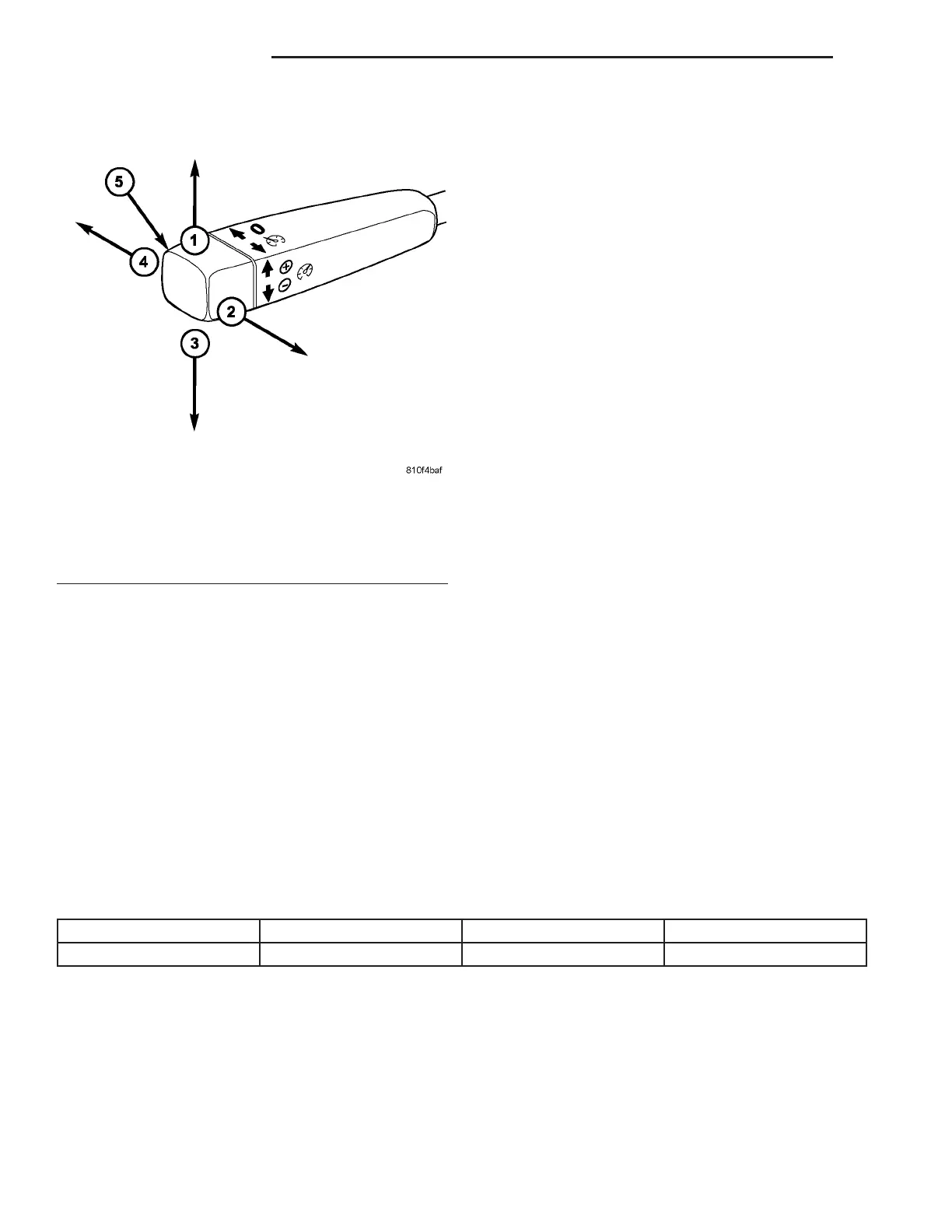
Fig. 2 SPEED CONTROL SWITCH FUNCTIONS
1 - SET / ACCELERATE
2 - RESUME SET SPEED
3 - SET / DECELERATE
4 - OFF
5 - SWITCH HANDLE
8P - 2 S P EED CON T R OL VA