SWI T CH
REMOVAL
The speed control switch is mounted to the back of
the multi-funct ion switch (Fig. 3). The multi-fu nction
switch must be removed first to gain access to the
speed control swit ch mount ing screw.
(1) Remove and isolate nega tive bat tery cable from
ba t t er y.
(2) Remove multi-funct ion swit ch. Refer to Multi-
Function Swit ch Remova l/Insta lla tion .
(3) Remove swit ch mount ing screw (F ig. 4).
(4) Remove speed contr ol switch from m ulti-func-
tion switch.
(5) Unplug pigta il electrical connect or (F ig. 3) from
ins trume nt p anel wiring harne s s.
INSTALLATION
The speed control switch is mounted to the back of
the m ult i-funct ion swit ch (Fig. 3).
(1) Position speed contr ol switch to back of multi-
function switch .
(2) In st all switch mounting screw (F ig. 4). Refer t o
Torque Specifica tions.
In st all mu lti-funct ion switch. Refer to Mu lti-Fun c-
tion Switch Removal/In st allation.
(3) Plug pigtail electrical conn ector (Fig. 3) int o
ins trume nt p ane l w iring harne s s . B e s ure w ire s are
not pinch ed.
(4) In st all negative batt ery ca ble t o bat tery.
Fig. 3 SPEED CONTROL SWITCH LOCATION
1 - SWITCH HANDLE
2 - PIGTAIL ELECTRICAL CONNECTOR
3 - MULTI-FUNCTION SWITCH
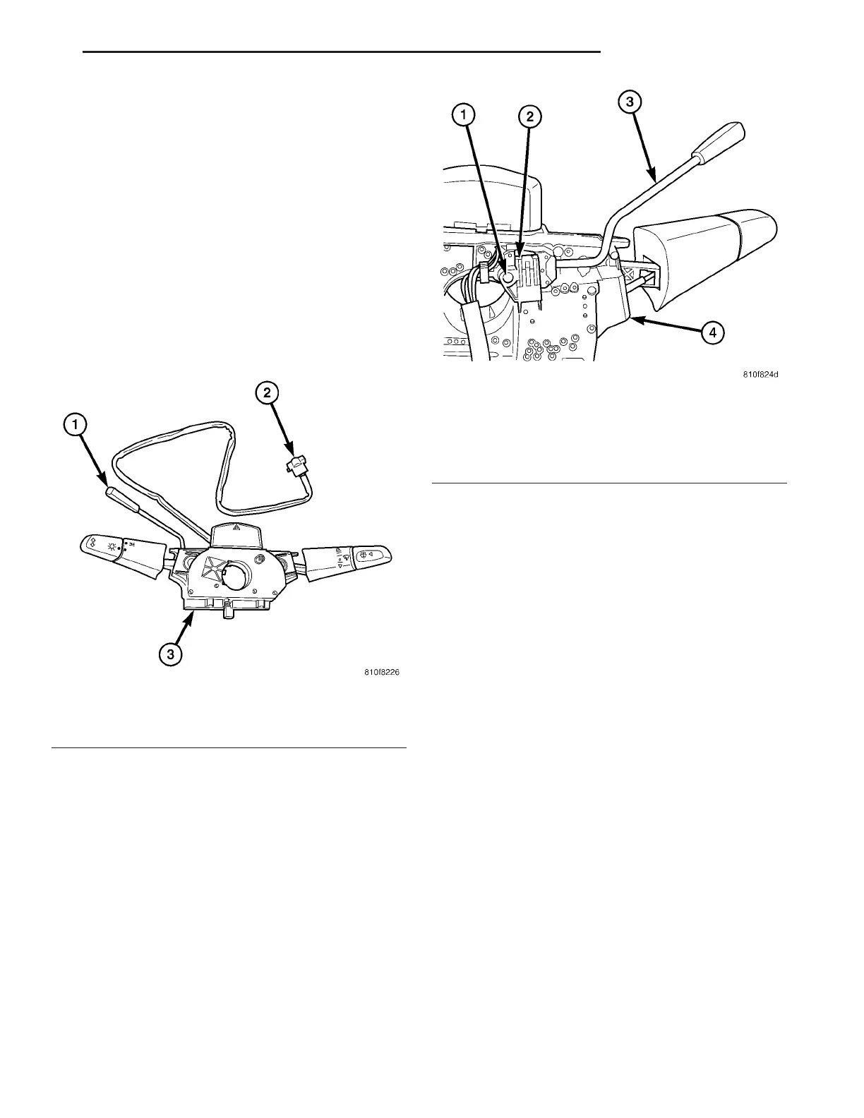
Fig. 4 SPEED CONTROL SWITCH REMOVAL /
INSTALLATION
1 - SWITCH MOUNTING SCREW (1)
2 - SPEED CONTROL SWITCH
3 - SWITCH HANDLE
4 - MULTI-FUNCTION SWITCH
VA SPEED CONTROL 8P - 3