COLU M N
TABLE OF CONTENTS
page page
COLUMN
SPECIFICATIONS - TORQUE CHART .........4
INTERMEDIATE SHAFT
REMOVAL .............................4
INSTALLATION ..........................5
KEY/LOCK CYLINDER
REMOVAL .............................5
INSTALLATION ..........................6
STEERING WHEEL
REMOVAL .............................6
INSTALLATION ..........................6
COLU M N
SPECIFICATIONS - TORQUE CHART
TORQUE SPECIFICATIONS
DESCRIPTION N·m Ft. Lbs. In. Lbs.
Steering Wheel With Air-
bag To Steering Shaft
80 59 —
Jacket Tube For Steering
Shaft To Waist Rail
25 18 221
U-Joint To Steering Gear
Shaft
24 18 212
INTERMEDIATE SHAFT
REMOVAL
(1) Disconn ect the ground cable from th e bat tery.
(2) Remove the air bag m odu le from the steerin g
wh eel.
(3) Turn t he steerin g wheel and lock th e steering
wheel in the stra igh t ahead position. Th e p o s i t io n
of the steering gear must not be altered again
fo r t h e ent ire d ura t io n o f t h e w o r k p ro c e d ure .
(4) Remove the electrical center.
(5) Remove the st eering wheel bolt .
(6) Remove the steerin g wheel from the steer ing
column.
(7) Remove the clockspring. Unscrew the retain-
ing bolts just enough to be able to remove the
clockspring. Do not twist or disassemble the
clockspring.
(8) Remove the combin ation switch .
(9) Disconn ect the elect rical connector for t he igni-
tion lock.
(10) Remove the spr ing for the brake peda l from
the st eering column.
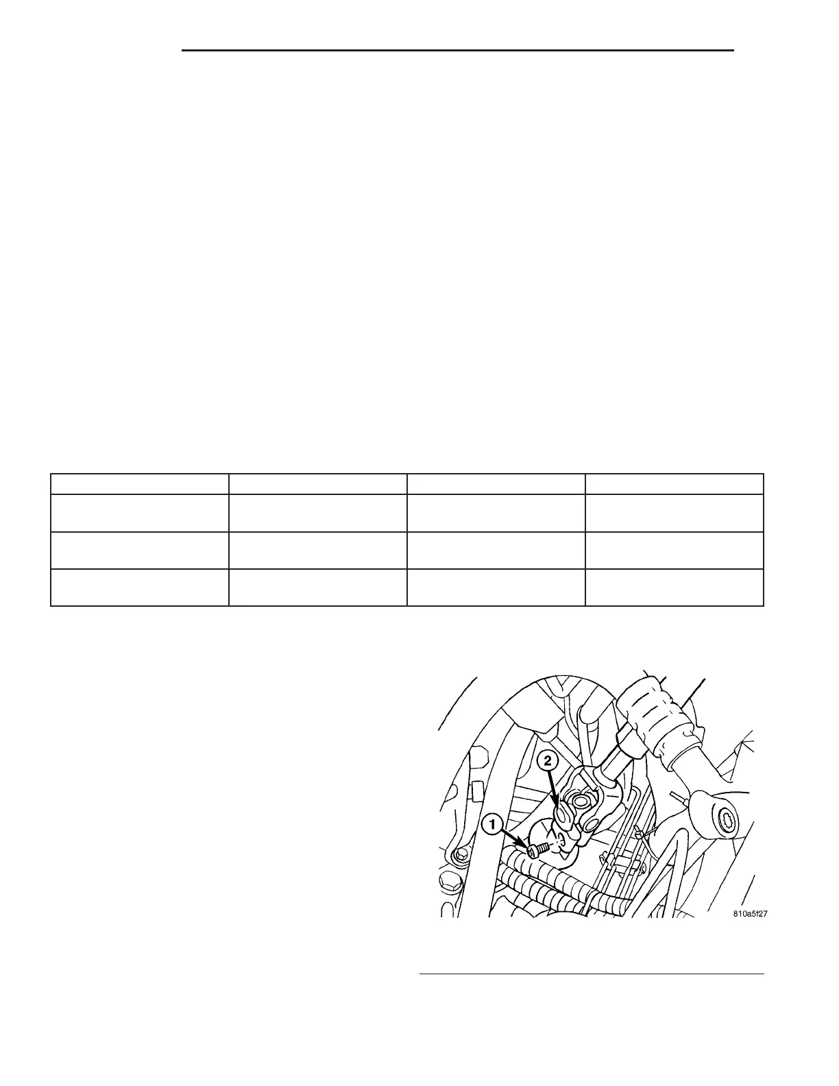
(11) Remove th e fit ted bolt fr om the u niversal joint
(Fig. 1).
(12) Remove the bolts in th e steerin g column
bracket (Fig. 2).
Fig. 1 U-JOINT REMOVE / INSTALL
1 - FITTED BOLT
2 - U-JOINT
19 - 4 COL U MN VA