(13) Remove th e steer ing shaft with th e univer sa l
joint off th e steer ing gea r drive sh aft (Fig. 1).
(14) Pull th e steer ing shaft out of the rubber grom-
met in the cab floor.
INSTALLATION
(1) In st all th e steering sha ft thr ough t he r ubber
grommet in the cab floor. Ensure that the rubber
grommet is properly seated.
(2) In st all th e steer ing shaft with the un iversal
joint onto the st eering gear shaft (Fig. 1).
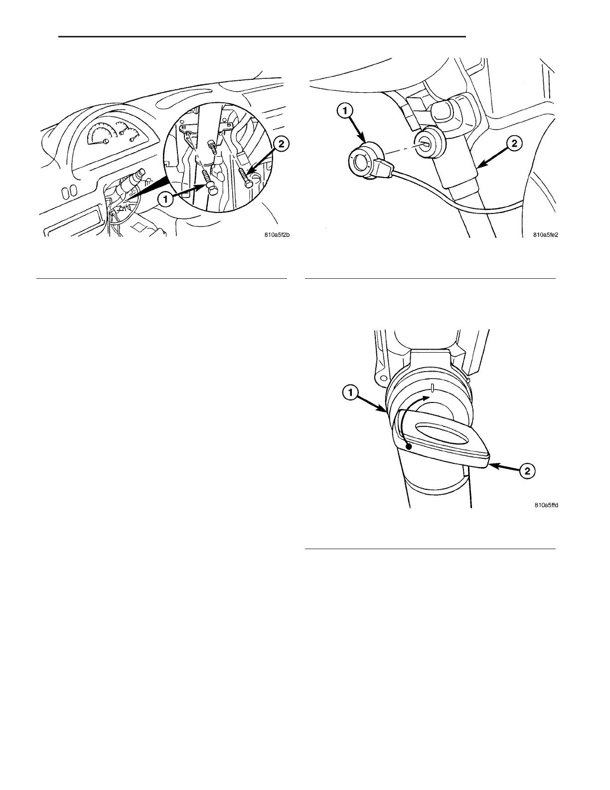
(3) In st all the bolts in the steerin g column br acket
(Fig. 2). Tighten to 24 N·m (18 ft. lbs.).
(4) In st all the u niversal join t on t he st eering gear
sh aft (Fig. 1). Tigh ten to 24 N·m (18 ft. lbs.).
(5) In st all th e sprin g for the brake pedal to the
st eering column.
(6) Reconnect t he electrical connect or to th e ign i-
tion lock.
(7) In st all the combinat ion switch.
(8) In st all the clockspr ing.
(9) In st all the steering wheel.
(10) Install the electrical center.
(11) Reconnect t he gr ound cable to the batt ery.
KEY / LOCK CYLINDER
REMOVAL
(1) Remove the secu ring cover for th e central elec-
tronics.
(2) Remove the st eering column shr oud.
(3) Remove the t ransponder coil off the ignition
lock (Fig. 3).
(4) In sert the key in to th e ignit ion lock.
(5) Turn the ign ition key to the first detent (Fig.
4).
(6) Turn the cap a 1/4 tur n to th e left (Fig. 5).
Fig. 2 STEERING COLUMN BOLTS
1 - BOLT
2 - COLUMN BOLT
Fig. 3 TRANSPONDER
1 - TRANSPONDER
2 - STEERING COLUMN
Fig. 4 IGNITION LOCK FIRST DETENT
1 - LOCK HOUSING
2 - FIRST DETENT WITH KEY INSTALLED
VA COLUMN 19 - 5