(7) Remove cap together with the lock cylinder off
the ign ition lock (Fig. 6).
INSTALLATION
(1) In st all th e cap together with the lock cylinder
onto t he ignition lock (Fig. 6).
(2) Turn the cap a 1/4 tur n to th e right.
(3) Turn the ign ition key to the first detent (Fig.
4).
(4) Remove the ignition key from the ignition lock.
(5) In st all th e tr ansponder coil onto the ignition
lock (Fig. 3).
(6) In st all th e steering column shroud. Pay atten-
tion to the cables routed under the steering col-
umn cover. Do not trap the cables.
(7) In st all the cover for th e cent ral elect ronics.
ST EERI N G WH EEL
REMOVAL
(1) Disconn ect the ground cable on the battery.
(2) Remove the air bag m odu le from the steerin g
wh eel.
(3) Turn t he steerin g wheel and lock th e steering
wheel in the stra igh t ahea d position (F ig. 7).
(4) Remove the st eering wheel bolt (F ig. 7).
(5) Remove the steerin g wheel from the steer ing
column (Fig. 7).
INSTALLATION
(1) In st all th e steerin g wheel onto t he column (Fig.
7).
(2) In st all the steer ing wheel bolt (F ig. 7). Tight en
to 80 N·m (59 ft. lbs.).
(3) In st all the air bag m odu le.
(4) Reconnect t he battery ground cable.
(5) Reset all th e times an d encode th e radio.
(6) Perfor m a r oad test to check t he posit ion of t he
steer in g wheel.
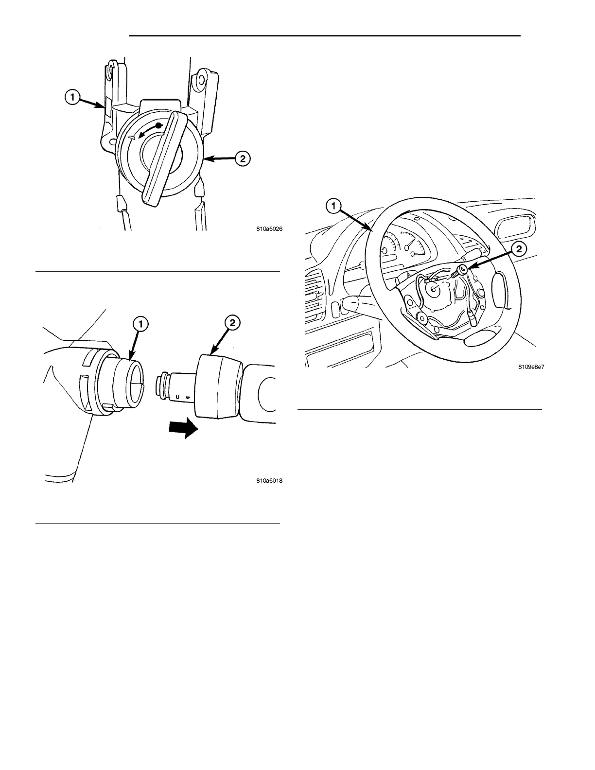
Fig. 5 1/4 TURN LEFT
1 - STEERING COLUMN
2 - 1/4 TURN TO THE LEFT
Fig. 6 LOCK CYLINDER OFF THE IGNITION LOCK
1 - LOCK HOUSING
2 - LOCK CYLINDER
Fig. 7 STEERING WHEEL
1 - STEERING WHEEL
2 - STEERING WHEEL BOLT
19 - 6 COL U MN VA