GEAR
TABLE OF CONTENTS
page page
GEAR
DESCRIPTION ..........................7
REMOVAL .............................7
INSTALLATION ..........................7
SPECIFICATIONS - TORQUE CHART .........8
GEAR
DESCRIPTION
A rack and pinion st eering gears (Fig. 1) is made
up of two ma in components, the pin on sha ft an d the
rack. The gea r cannot be adjusted or internally ser-
viced. If a malfunction or a fluid leak occur s, the gear
must be r eplaced as an assembly.
REMOVAL
(1) Siphon t he power steerin g fluid out of the res-
ervoir.
(2) Raise and support the vehicle.
(3) Remove the front wh eels.
(4) Remove the stabilizer ba r fr om th e upper pa rt
of t he stabilizer link (Refer to2-SUSPENSION/
FRONT/STABILIZER LINK - REMOVAL).
(5) Remove t he ou ter tie rod en d nut s and sepa-
rate th e tie r ods from the steerin g knu ckles (Fig. 2)
using specia l tool C-3894–A.
(6) Remove the left outer t ie rod end fr om the
steer in g gear.
(7) Remove both spring cla mp plat es (Refer to 2 -
SUSPENSION/FRONT/SPRING CLAMP PLATES -
REMOVAL).
(8) Remove both t he high pr essu re and return
hoses from the steer ing gear (Refer t o 19 - STEE R-
ING/PUMP/H OSES - REMOVAL) (F ig. 2).
(9) Remove the steer ing sh aft clam ping bolt from
the st eering gear (F ig. 2).
(10) Separa te th e univer sa l joint from th e st eering
gear (F ig. 2).
(11) Remove t he st eering gea r bolts from the front
axle.
(12) Remove th e steering gear by sliding it towar d
the passengers side of the vehicle an d then tilt down-
ward on the drivers side and r emove from veh icle.
INSTALLATION
(1) In st all the gea r to the vehicle.
NOTE: Steering gear must be torqued in a three
step procedure below.
(2) In st all th e steer ing gear bolts (F ig. 2). Tighten
to an initia l torque of 25 N·m (18 ft. lbs.) Then
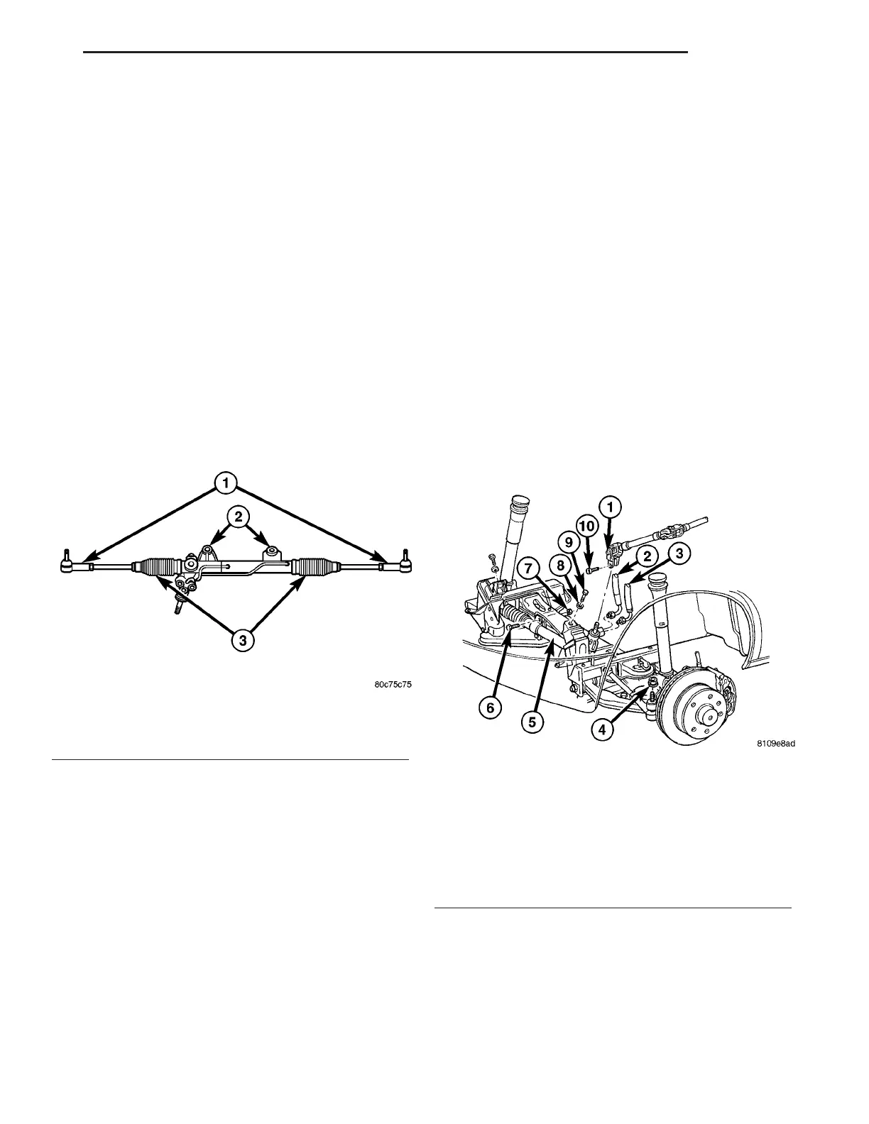
Fig. 1 STEERING GEAR
1 - OUTER TIE ROD ENDS
2 - MOUNTING BUSHINGS
3 - BELLOWS
Fig. 2 STEERING GEAR REMOVAL / INSTALL
1 - U-JOINT
2 - HIGH PRESSURE POWER STEERING HOSE
3 - RETURN HOSE
4 - OUTER TIE ROD END RETAINING NUT
5 - STEERING GEAR
6 - STEERING GEAR RETAINING BOLT
7 - STEERING GEAR NUT
8 - WASHER
9 - ENGINE MOUNT BOLT
10 - U-JOINT CLAMPING BOLT
VA GEAR 19 - 7