Command Valve
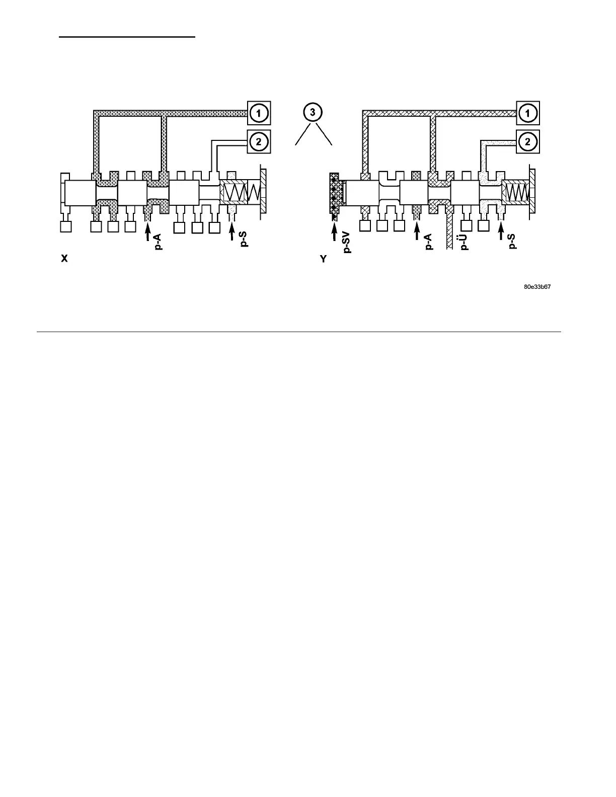
Each sh ift gr oup possesses one command valve (3)
(Fig. 104). The 1-2 / 4-5 an d 2-3 command valves are
insta lled in the shift valve housing, t he 3-4 command
valve is insta lled in the va lve housing. The com mand
valve switch es the shift group from t he station ary
ph ase to the shift phase a nd back aga in.
Fig. 104 Command Valve
1 - HOLDING CLUTCH B1
2 - DRIVING CLUTCH K1
3 - 1-2/4-5 COMMAND VALVE
VA AUTOMATIC TRANSMISSION NAG1 - SERVICE INFORMATION 21 - 109