FLU I D AN D FI LT ER
DESCRIPTION
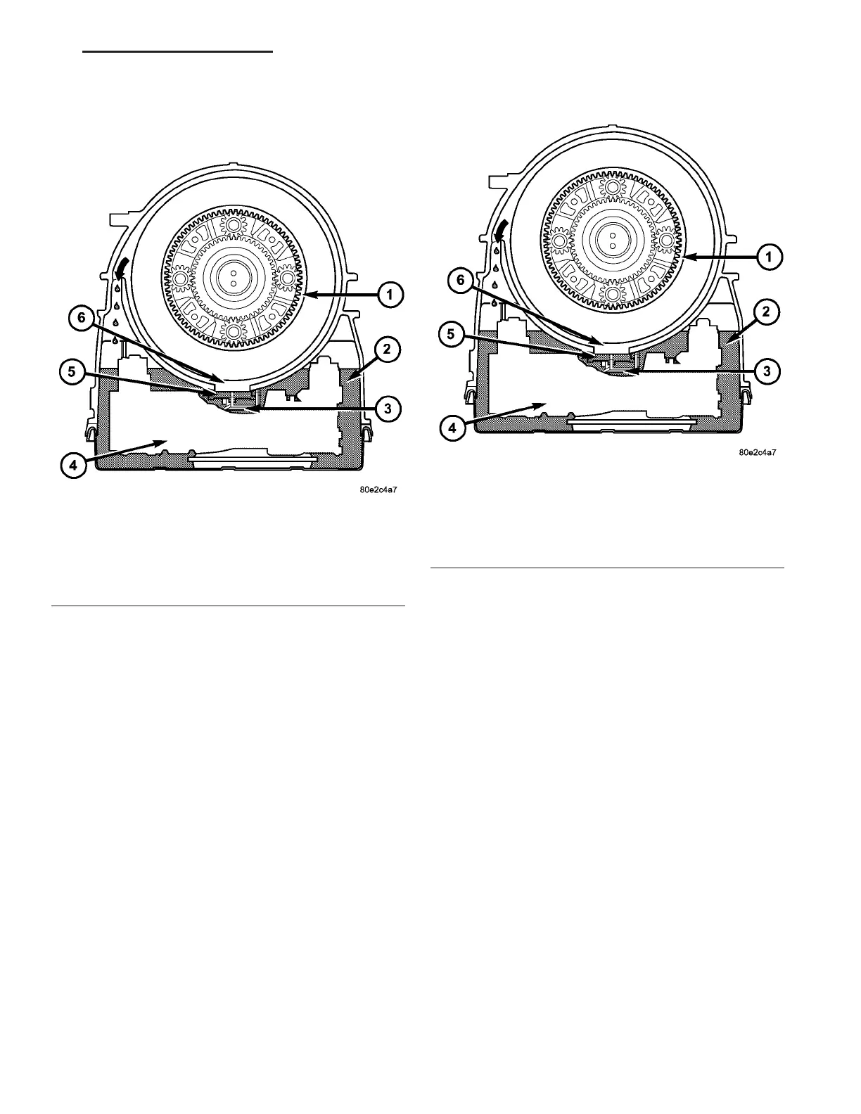
The oil level control (Fig. 147) is loca ted on the
electrohydr aulic un it (4) and consists of the floa t (5)
which is integra ted in to th e electrohydra ulic un it.
The float is posit ioned to plug the open ing (6)
between the oil gallery (2) an d gearset chamber (1) so
that th e rota ting gea rsets do not spla sh abou t in oil
as the oil level rises. The oil level control reduces
power loss and prevent s oil from being thrown out of
the t ransmission housing a t high oil t empera tur es.
OPERATION
With low oil levels, t he lubr icat ing oil which flows
constan tly out of the gearset, flows ba ck to oil gallery
(2) thou gh the openin g (6). (Fig. 148) If the oil level
rises, the oil presses t he float (5) again st the housing
openin g (6). The float (5) therefor e sepa rates the oil
galler y (2) from t he gear set cham ber (1). The lubr i-
cating oil which contin ues to flow out of th e gea rsets
is thrown a gainst the housin g wa ll, incorpor ated by
the rotatin g pa rts and flows back into the oil gallery
(2) through t he upper open ing (arr ow).
DI AGN OSI S AN D T EST I N G
EFFECTS OF INCORRECT FLUID LEVEL
A low fluid level a llows t he pump to take in air
alon g with the fluid. Air in the flu id will cause fluid
pr essu res t o be low and develop slower t han normal.
If the t ran smission is overfilled, the gears chur n the
fluid into foam. This aerat es t he flu id and causing
the sa me condition s occurrin g with a low level. In
eith er case, air bubbles cause fluid overh eating, oxi-
da tion, and va rnish buildup which int erferes with
valve an d clu tch operat ion. Foaming also causes fluid
expan sion which ca n resu lt in flu id overflow from the
transmission vent or fill t ube. F luid over flow can eas-
ily be m istaken for a leak if inspection is not car eful.
Fig. 147 Fluid Level Control
1 - GEARSET CHAMBER
2 - OIL GALLERY
3 - SHELL OF ELECTROHYDRAULIC UNIT
4 - ELECTROHYDRAULIC UNIT
5 - FLOAT
6 - OPENING
Fig. 148 Fluid Level Control
1 - GEARSET CHAMBER
2 - OIL GALLERY
3 - SHELL OF ELECTROHYDRAULIC UNIT
4 - ELECTROHYDRAULIC UNIT
5 - FLOAT
6 - OPENING
VA AUTOMATIC TRANSMISSION NAG1 - SERVICE INFORMATION 21 - 131