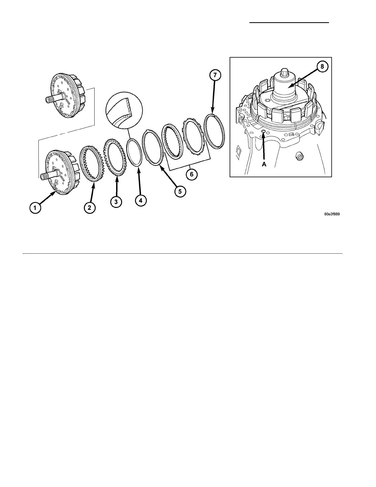
(2) Remove snap-r ing (7) (Fig. 168).
(3) Remove multiple-disc pa ck (6) and disc sprin g
(5) from ou ter multiple-disc carrier. Note which
clutch disc is removed just prior t o t he disc spring (5)
for re-a ssem bly. If the clutch discs a re r e-used, this
disc mu st be returned to its origin al position on top
of the disc spring.
(4) Pla ce t he Multi-use Sprin g Compressor 8900
(8) (Fig. 168) on disc spring (3) and compress t he
spring unt il t he snap-ring (4) is exposed.
(5) Remove snap-r ing (4).
(6) Remove pist on (2) from th e outer mu ltiple-disc
carrier by carefully blowing compressed air in to the
bore (A).
Fig. 168 Holding Clutch B1
1 - HOLDING CLUTCH B1 OUTER CARRIER 5 - DISC SPRING
2 - PISTON 6 - MULTIPLE DISC PACK
3 - DISC SPRING 7 - SNAP-RING
4 - SNAP-RING 8 - MULTI-USE SPRING COMPRESSOR 8900
21 - 144 AUTOMATIC TRANSMISSION NAG1 - SERVICE INFORMATION VA