ASSEMBLY
NOTE: Check vulcanized gasket, replace if neces-
sary.
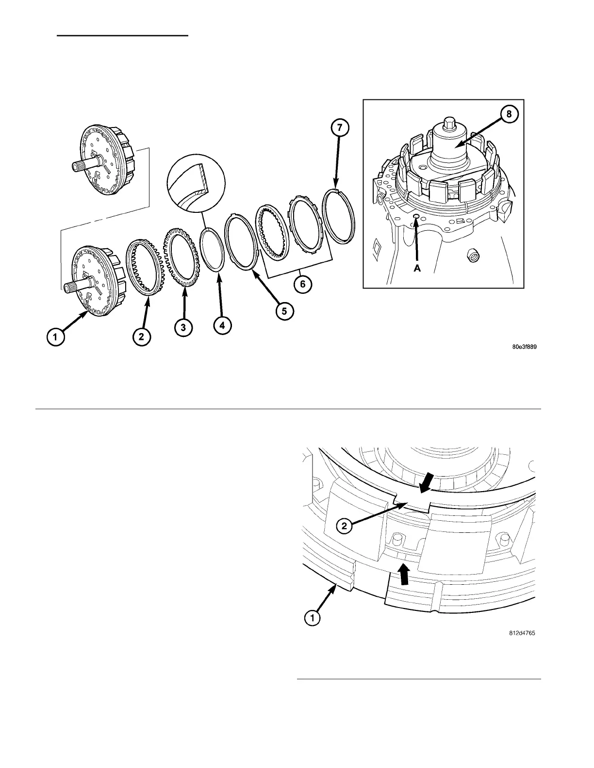
(1) In st all piston (2) (Fig. 169) in outer multiple-
disc car rier (1).
(2) Pla ce compressor (8) on disc spring (3) and
compress un til the groove of th e snap-r ing is exposed.
NOTE: The collar of the snap-ring must point
towards the multiple-disc pack. After installing,
check snap-ring for correct seat.
(3) In sert snap-r ing (4) (Fig. 169).
(4) In sert disc spring (2) (Fig. 170) in the outer
multiple-disc car rier. Observe the disc spring (2)
insta lla tion position. The lugs of th e disc spring (2)
Fig. 169 Holding Clutch B1
1 - HOLDING CLUTCH B1 OUTER CARRIER 5 - DISC SPRING
2 - PISTON 6 - MULTIPLE DISC PACK
3 - DISC SPRING 7 - SNAP-RING
4 - SNAP-RING 8 - MULTI-USE SPRING COMPRESSOR 8900
Fig. 170 Install the Disc Spring
1 - B1 MULTIPLE-DISC CARRIER
2 - DISC SPRING
VA AUTOMATIC TRANSMISSION NAG1 - SERVICE INFORMATION 21 - 145