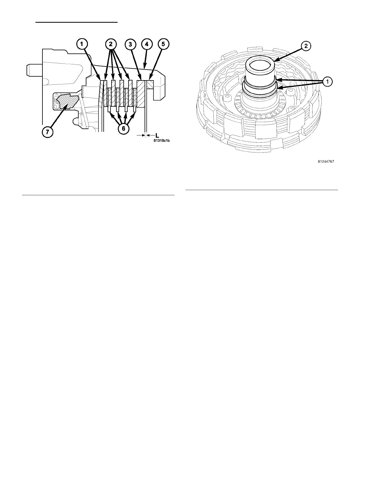
(10) For tr ansmissions u sing single sided friction
discs, use a feeler gauge t o determ ine the play “L”
(Fig. 173) a t three points between the sn ap-rin g (5)
and outer multiple-disc (3). During the mea su remen t,
the sna p-ring (5) must cont act the upper bea rin g sur-
face of the groove in th e ou ter multiple-disc carrier
(4). The correct clear ance is 2.2-2.6 mm (0.087-0.102
in.) for four frict ion disc ver sions, 2.4-2.8 mm (0.095-
0.110 in.) for six disc versions, and 2.6-3.0 mm
(0.102-0.1 18 in . ) for eigh t disc ver sions.
(11) Adjust wit h sna p-r ing (5), if necessa ry. Sna p-
rings a re available in thickn esses of 2.6 mm (0.102
in.), 2.9 mm (0.114 in.), 3.2 mm (0.126 in.), 3.5 mm
(0.138 in.), 3.8 mm (0.150 in.), and 4.1 mm (0.162
in.).
(12) Install the t eflon r ings (1) (Fig. 174) on to the
B1 plate car rier hub (2).
(13) Coat Teflon rin gs (1) ligh tly with grea se and
inser t in the groove so that the join t remains
toget her.
Fig. 173 B1 Clutch Stack-up - Single Sided Discs
1 - DISC SPRING
2 - OUTER MULTIPLE DISC
3 - OUTER MULTIPLE DISC - 4.0 mm (0.158 IN.)
4 - B1 OUTER CARRIER
5 - SNAP-RING
6 - INNER MULTIPLE DISCS
7 - PISTON
Fig. 174 Install the Teflon Rings
1 - TEFLON RINGS
2 - PLATE CARRIER HUB
VA AUTOMATIC TRANSMISSION NAG1 - SERVICE INFORMATION 21 - 147