HOLDING CLUTCH B2
DISASSEMBLY
(1) Remove snap r ing (1) (Fig. 175).
(2) Take mu ltiple-disc pack B2 (2) a nd disc spring
(3) out of the outer multiple-disc ca rrier B2 (8). The
outer m ultiple-disc carr ier for the multi-disc holding
clutch B2 is t he piston for the mu ltiple-disc holding
clutch B3 a t the same tim e. Note wh ich clutch disc is
removed just prior to th e disc spr ing (3) for re-assem-
bly. If t he clu tch discs are r e-used, th is disc mu st be
retu rned to its origin al position on top of the disc
sprin g.
(3) Pla ce t he Multi-u se Spr ing Compressor 8900 on
the spring disc (14) and compress the spring until
the groove for the sn ap-ring is exposed.
(4) Remove snap-r ing (16) (Fig. 175).
(5) Remove spring plate (15) and disc spring
(14).
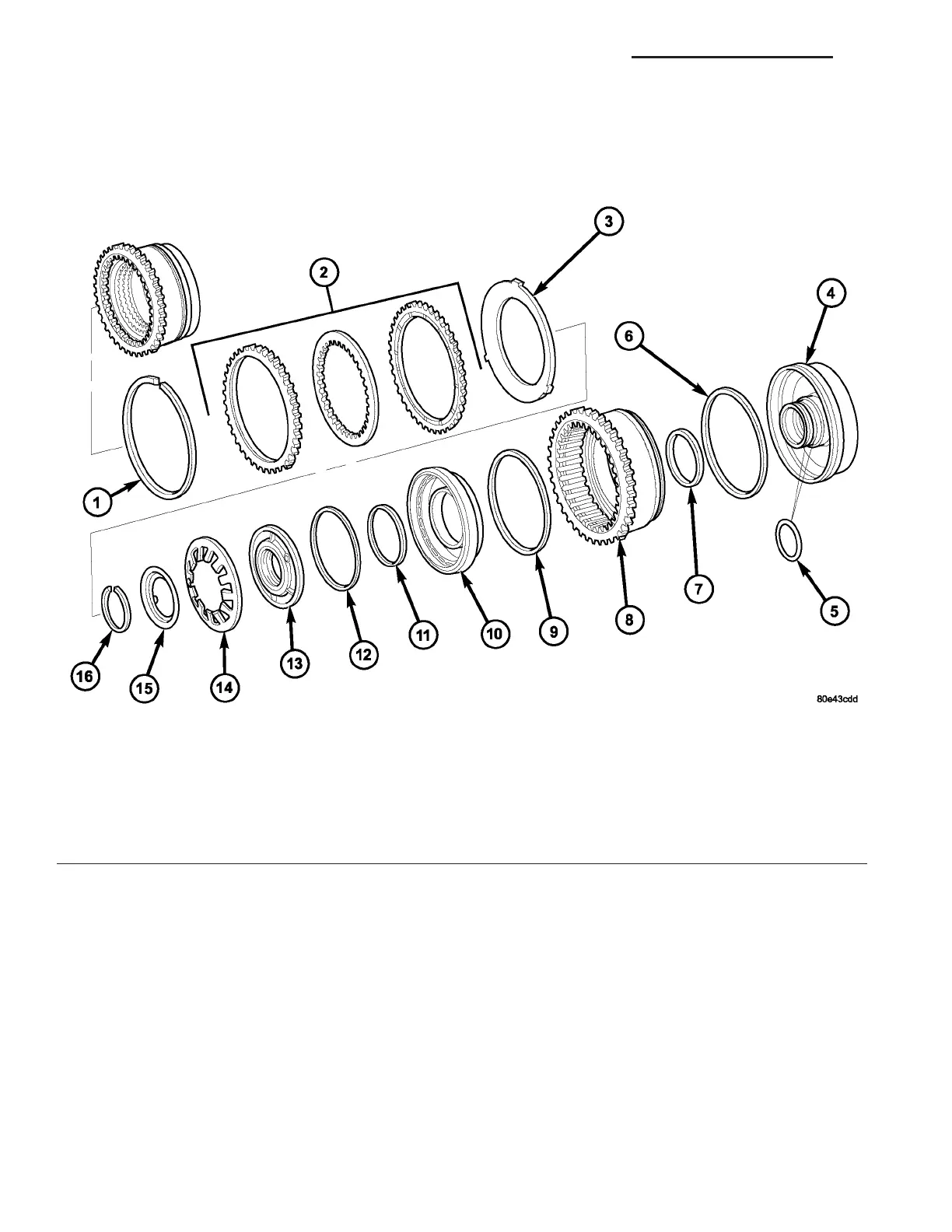
Fig. 175 Holding Clutch B2
1 - SNAP-RING 9 - B2 PISTON SEALING RING
2 - MULTIPLE DISC PACK 10 - B2 PISTON
3 - DISC SPRING 11 - PISTON GUIDE SEALING RING
4 - B2 AND B3 PISTON GUIDE 12 - PISTON GUIDE SEALING RING
5 - O-RING 13 - PISTON GUIDE RING
6 - B3 PISTON SEALING RING 14 - PISTON BACK PRESSURE DISC SPRING
7 - B3 PISTON SEALING RING 15 - SPRING PLATE
8 - B3 PISTON/B2 OUTER DISC CARRIER 16 - SNAP-RING
21 - 148 AUTOMATIC TRANSMISSION NAG1 - SERVICE INFORMATION VA